Is There a More Accurate Means to Calculate Tonnage?
Molders have long used the projected area of the parts and runner to guesstimate how much tonnage is required to mold a part without flash, but there’s a more precise methodology.


At its most basic level, injection molding consists of shooting molten plastic inside a closed mold that is subsequently opened after the plastic has cooled down to the ejection temperature. The pressures that are used to inject the plastic are high enough to separate the two halves of the mold during the injection process. To prevent this, a force defined as tonnage is applied on the two mold halves to keep them together during injection.
When selecting which molding machine is suitable for running a given mold, there are five plastic-related machine specifications that must be considered: tonnage, maximum machine shot capacity, maximum available injection pressure, maximum available injection speed and the maximum settings for the barrel temperature. There are, of course other specifications that must be satisfied such as ensuring the mold can fit between the platens, but considerations like these are not plastic related.


A thin-wall part and a thick-wall part with the same projected areas can end up requiring different tonnages.
The pressure inside the cavity to make an acceptable part will depend mainly on the part design. The plastic will need to fill and then pack the cavity with additional plastic to compensate for the shrinkage that occurs as the plastic cools. As the plastic transitions from fountain flow to fill the cavity, the average pressure inside the tool can range from 4,000 to 8,000 psi, depending on the part design. Given that 1 ton is equal to 2,000 lbs, the average cavity pressure is between 2 and 4 tons/in2. This calculation is how material manufacturers estimate the required tonnage for their resins.
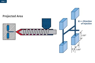
FIG 1 Projected area considers the surface area of the runner system and parts in the direction of injection. Image Credits: S. Kulkarni
To better understand the required-tonnage calculation, let’s say the pressure inside the cavity is 5,000 psi which equals 2.5 tons. This pressure can open the mold halves if there is no counterforce being applied on the mold halves. If the projected part area on which the pressure is applied is 1 in2, then we will need a force slightly more than 2.5 tons to counter the pressure trying to push the mold open. Projected area is defined as the 2D space on which the plastic pressure is applied looking in the direction of injection. Note that it is not the surface area of a part (Figure 1).
Molders use a simple formula based on the above to calculate the required tonnage. Referring to Figure 2, if the projected area of one cavity is 6 in2 and this is a 4-cavity mold, the projected area for the four cavities is 6 × 4 = 24 in2. If the projected area for the runner is 4 in2, then the total projected area for the mold is 28 in2. If the suggested tonnage requirement by the material supplier is 4 tons/in2, then the tonnage required for this mold is 112 tons (28 × 4). While the above formula is a good estimation of the required tonnage for a given mold, there are several limitations to this type of a calculation.
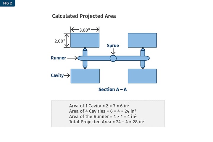
FIG 2 Calculating the total projected area of the sprue, runner and cavities gives molders a figure they can use to estimate required clamp force tonnage.
Through Thick and Thin
Injection pressure is used to fill the cavity with plastic, while packing pressure compensates for shrinkage and holding pressure holds the plastic inside the cavity until the gate area freezes off. Consider a large round trash bin used to collect yard waste. The flow-length-to-thickness ratio (L/T ratio) of this bin is large and therefore the injection pressures required to fill the cavity are high. Except for the handle area, most of the part consists of a thin wall and therefore the pack and hold pressures are relatively smaller.
Now consider a part design that has a very thick wall. In such a case, the injection pressure will be low but the pack and hold pressures will be high. In some cases, they can be much higher than the injection pressure. Therefore, a thin-wall part and a thick-wall part with the same projected areas can end up requiring different tonnages.
The tonnage calculation should not be based on projected area alone.
Visualize a long 12-inch part with one side gate. Now picture the same part now with two gates, one at each end. With our knowledge of molding, we know that the one with two gates will require lower injection pressures, and lower pack and hold pressures thereby reducing the required tonnage for the mold. Therefore, the number of gates and even the types of gates will have an effect on the required tonnage. An edge gate will fill the part easier than a sub gate or a cashew gate.
Extending the discussion using the same 12-inch part, if we move the one gate from the end of the part to its center, we can follow the same theory and realize that we will need lower pressure in the center-gated part and therefore less tonnage for the mold compared to the side-gated part.
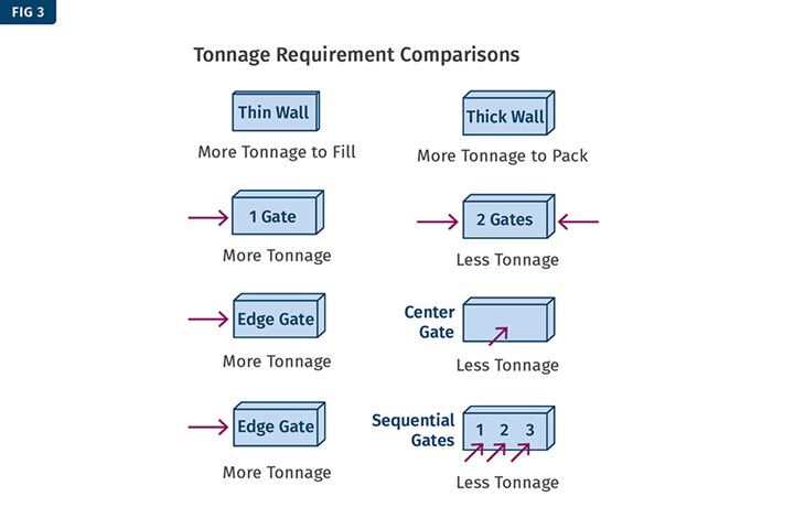
FIG 3 Part thickness and the number, style and location of the gates for a given part will all impact tonnage requirements.
Large parts such as car bumpers and automotive side panels often use sequential valve gating for the mold-filling process. The projected area of these parts is very large, but because each valve gate opens one at a time or in a certain sequence, the plastic material is still not beginning to cool, allowing the use of lower pressures to fill and pack the parts out. Most of these parts can be molded on 1,500-to-2,000 ton machines, but if the projected area calculation was applied, it would mandate a 5,000- or 6,000-ton machine.
Figure 3 summarizes the above discussions. Furthermore, we must consider that the part’s orientation in the mold will influence the projected area (Figure 4). They are the exact same part, but the shading shows the stark differences in projected area. In the second part, the projected area is much lower than in the first, but this does not mean we can get away with lower tonnage because the flow length in the direction of mold open is much longer.
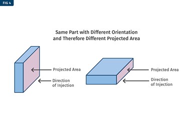
FIG 4 The same part could have very different projected areas based on its orientation within the mold.
There are different types of side mechanisms to mold side features on the part. Slides can be on angle pins, or they can be hydraulically activated. If they are on angle pins, then the load in the direction of mold open must be calculated because this force will open the mold and therefore affects tonnage. If they are hydraulically activated, then the force of activation need not be taken into consideration.
A New Method for Tonnage Calculation
Given what we have discussed so far, it’s clear that the tonnage calculation should not be based on projected area alone. There are several other factors that must be considered, including part thickness, flow lengths, gate position, gate number, gate type, gating mechanisms, orientation of the part in the mold, and the presence and type of slide mechanism used. As you dig deeper, you may come up with additional factors. For instance, if you consider venting, you will realize that it will also affect the required tonnage.
Most molders will select a machine based on the projected area formula for lack of a better resource. When the mold is delivered to the molding floor, most processors will set the tonnage to the maximum available on the machine — not an ideal scenario.
Optimizing this scenario is a simple, logical procedure that takes just 10 to 15 minutes. For the mold under consideration, set the tonnage based on about 3.5 to 4 tons/in2. For the example, let’s say the machine tonnage was set to 60 tons. Develop the molding process using Scientific Molding and Design of Experiments principles. Make sure the final cushion of this process is optimized. For example, for a 35- to 60-mm screw diameter, cushion values should be between 0.15 to 0.25 inch (around 5 to 8 mm).
Most processors will set the tonnage to the max available on the machine — not an ideal scenario.
Next, start reducing the machine’s set tonnage in steps of 5 tons and collect the complete shot including parts and runners. Refer to Figure 5 where the shot weight was plotted against reducing tonnage. The graph shows that as the tonnage is reduced, the shot weight increases very slightly until a tonnage value where the mold halves separate, and then there is a sudden increase in the shot weight. In this case, that value was 40 tons and at 35 tons the parts had noticeable flash. Because the noticeable weight increase occurred at 40 tons, the tonnage should be set between 45 and 50 tons.
You can also plot a part dimension versus tonnage (Figure 5). Choose a part dimension in the direction of mold open and a similar trend will be seen where the part dimension will increase when the mold halves separate. This graph is also food for thought on how dimensions could change with tonnage. A part may be in specification on a 50-ton press but not on a 75-ton press (or vice versa) even though the plastic processes on the two machines are identical.
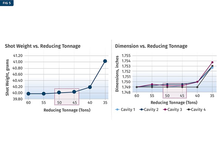
FIG 5 By recording shot weight as tonnage is reduced to the point of flash, or isolating and tracking a specific part dimension, molders can identify the appropriate tonnage for the part.
The reason for having a low cushion value during these studies is to protect the mold from over flashing with the excess plastic in the cushion. Having a large cushion can create a lot of flash that can end up in slides, vents and other sensitive areas of the mold. This could damage the mold components and potentially require the mold to be taken to the tool room for cleanup and repair. This reminds me of the oft-made molding-floor quip: “We clean the vents when we flash the mold.” While this might be funny to some, the statement has no technical value, and is most definitely not a joke to tooling personnel!
In summary, there are several factors that will affect tonnage for a given mold and, ultimately, the common formula to calculate tonnage does not work very well. Tonnage for a given mold must be optimized in order to have a robust, repeatable and a reproducible process that will deliver parts that meet the required quality during every production run.
ABOUT THE AUTHOR: Suhas Kulkarni is the founder and president of Fimmtech, San Diego, an injection molding service-oriented firm focusing on Scientific Molding. Fimmtech has developed several custom tools that help molders develop robust processes, and its seminars have trained hundreds of individuals. Kulkarni is an author of the best-selling book, “Robust Process Development and Scientific Molding,” published by Hanser Publications. Contact: 760-525–9053; suhas@fimmtech.com; fimmtech.com.
Related Content

The Effects of Temperature
The polymers we work with follow the same principles as the body: the hotter the environment becomes, the less performance we can expect.
Read More
PBT and PET Polyester: The Difference Crystallinity Makes
To properly understand the differences in performance between PET and PBT we need to compare apples to apples—the semi-crystalline forms of each polymer.
Read More
How to Select the Right Tool Steel for Mold Cavities
With cavity steel or alloy selection there are many variables that can dictate the best option.
Read More
Tunnel Gates for Mold Designers, Part 1
Of all the gate types, tunnel gates are the most misunderstood. Here’s what you need to know to choose the best design for your application.
Read MoreRead Next

Injection Molding: A Practical Approach to Calculating Residence Time
Toss the formulas. The best way to determine residence time is to conduct a simple experiment.
Read More
Clamp Tonnage: More Is Better...Right?
Determining the correct tonnage provides a foundation that must be rock-solid to avoid flash and damage. But applying excessive force can create problems with the part, mold, and machine.
Read More