
Demystifying the Devolatilization Process
Here are some practical guidance and simple tools to help you better understand the process and improve your operation.


Devolatilization is the process by which unreacted monomer, solvent, water, dissolved gases, or other undesirable volatile contaminants are removed from a polymer melt or solution. It is a mass-transfer process driven by a combination of thermodynamic and diffusional variables, with the design of the machine impacting both of these parameters. It is driven by superheating the volatile component, followed by exposing the melt or solution to a rapid decompression.
Single-screw or multi-screw extruders, or any number of custom or commercially available stripping devices such as wiped-film evaporators, have been used for devolatilization. The choice depends largely on the nature of the polymer to be stripped, the concentrations of volatiles, and other processing actions required for the product.


Despite the major commercial significance of devolatilization, little has been written on the topic. Only four texts have been published, and while the technical literature fares a bit better, most of the treatments are highly theoretical in nature and are few in number compared with topics such as screw design, mixing, morphology, etc.
A valuable source of design information on devolatilization, however, can be found in the patent literature. There is a plethora of patents and applications on screw and vent designs, non-screw devices, devolatilization processes, vent stuffers, etc., that when sifted through will contribute to a better understanding of the technology.
This column is intended as a general guide to the topic to help you better understand the process and perhaps improve your own operation. Discussion will focus strictly on single- and multi-screw devices. Devolatilization can be demystified by focusing on a few basic design and operational parameters and optimizing the conditions that will both protect the product and lead to the lowest residuals.
Elements of a Devolatilization Zone
Whether in a single-screw or multi-screw extruder, a typical devolatilization zone consists of a portion of a screw that is partially filled, isolated between two sections that are filled with melt. The filled regions are generally created by non-pumping elements—either compounders, blisters, or the die or exit of the extruder itself. Figure 1 shows a twin-screw design with multiple vents and the associated sealing element. Figure 2 shows the seals, screw elements, and associated pressure profile in a typical vented twin-screw extruder. In this instance, the second vent is used for an additional feeder, but the design is similar for devolatilization.
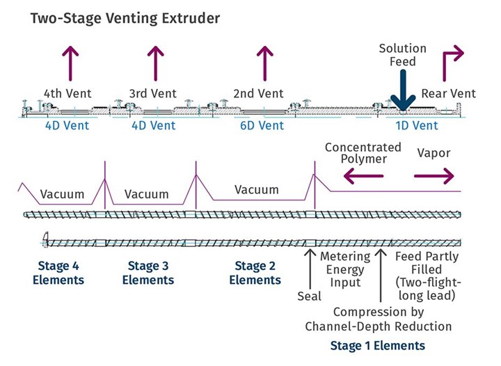
FIG 1 Shown here are the elements of the sealing, pumping and devolatilization screw sections. (Source: NFM Welding)
The rear or upstream seal is created by neutral or reverse compounding elements, a blister, a cylinder, or other restrictive means in the screw(s) so that air cannot pass from the rear of the extruder into the devolatilization (DV) zone. A neutral or reverse element forces the screw to be completely full at that seal, and for some turns of the screw upstream of that seal, to generate pressure to pump over the seal. This isolates the vacuum of the DV zone from the feed throat or other zones of the extruder.
The downstream or front seal is established in a similar manner, and often in the case of simple twin-screw operations or a single-screw extruder, the discharge of the extruder through a die serves as this seal. The goal again is to prevent vacuum from pulling through the downstream screw elements and disrupting the performance of the vent. Depending on the type of extruder, its length, and functional zones, the upstream seal may be fed from the melting zone of the extruder or may come from another mixing, blending, or venting operation. The downstream seal may be the die itself or discharge into another venting or additives-incorporation portion of the machine.
The design of the downstream seal is a bit more involved than the upstream seal, in that if the restriction is too tight or too close to the downstream face of the vent; if the throughput is too high; or the screw speed is too low, the filled portion of the screw or screws can back up under the vent opening and flood up into the vent, eventually blocking the outlet and piping to the vapor takeoff system.
For a twin-screw extruder, changes in the screw speed can alter the stability of the seals.
It is important that the operator understand how the vent will respond to changes in operating conditions. For a twin-screw extruder, changes in the screw speed can alter the stability of the seals. An increase in screw speed will shorten the filled length behind both the front and rear seals, making them more susceptible to failing. Decreases in screw speed will result in longer filled lengths behind each seal. For the downstream seal, this runs the risk of polymer backing up into the vent.
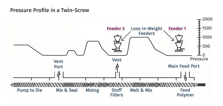
FIG 2 Seals, screw elements, and associated pressure profile in a typical vented twin-screw extruder. In this case, the second vent is used for an additional feeder, but the design is similar for devolatilization. (Source: Leistritz Extrusion)
Unit or Finishing Operation
Devolatilization is somewhat unique as a plastics process, since it can be employed both as a unit operation for isolation of a polymer melt from a solution, or as a finishing step for removing trace contaminants from a polymer that might otherwise harm the product or pose a risk to the public.
As a unit operation, devolatilization is an effective means of isolating a polymer from a solvent or monomer when the reaction is not carried out to completion. For a broad family of polymers whose polymerizations are highly exothermic (chain polymerizations such as acrylics and styrenics) conducting the polymerization in a solvent or the monomer itself provides a convenient way to control the exotherm. Typically, these reactions are carried to 40-60% completion in a stirred-tank reactor, followed by a stripping and recycling operation where the monomer or solvent is removed and recovered and recycled back to the stirred-tank reactor.
The mix is generally dropped into a multi-vent devolatilizing extruder or a combination of a flash device followed by an extruder. Typical machines would be fitted with two, three, or four vents that successively drop the solvent concentration to near zero.
As shown in Fig. 1, the reactor feeds (in this case, syrup) to the twin-screw extruder, which has four vents down the length of the machine. One of the significant advantages of screw extruders over other stripping devices is that the screw continually and evenly reheats the polymer following each devolatilization zone.
A good rule of thumb for vented machines is that each vent can bring the concentration of volatiles down by an order of magnitude. For example, a triple-vented machine can bring a 50%-solids feed down to less than 0.1% residuals with little difficulty.
The Push for Low Residuals
Devolatilization is almost invariably employed at or near the discharge of an extruder (or injection molding machine) to reduce or eliminate any residuals left in the melt. Reducing residuals to levels below a few hundredths of a percent is not uncommon.
The drivers for reduction in volatiles in finished polymers and plastics come from several quarters. First and foremost, residual solvent, monomers, or other volatile contaminants often have an adverse effect on the physical properties, physical appearance, stability, or aging performance of the final article. Residual volatiles will alter the color of a finished article and/or can adversely affect the UV light stability, and long-term strength.
Regulatory compliance—either industrial or governmental—will often dictate the level of residual contaminants in a plastic, especially for food and beverage, medical, or human-contact applications. Generally, the lower the residuals of any sort in a finished polymer, the safer and more durable the product.
A good rule of thumb for vented machines is that each vent can bring the concentration of volatiles down by an order of magnitude
In contrast with chain polymerizations, where devolatilization may be part of a unit operation, for step-growth polymerizations (nylons, PET, etc.) where there is less of a risk of thermal runaway, devolatilization will be employed to strip away the remaining monomers and other small molecules left over from the polymerization process itself.
In theory, it would be possible to strip a polymer melt completely of volatile residuals. There are two practical limitations on how low one can go. One is for certain types of polymers (chain-polymerization types, for example) that are subject to unzipping or depolymerizing with excessive heat and residence time. It is quite possible to have a well-designed vacuum vent and screw design run under full vacuum, only to see the residual volatiles increase as a result of unzipping or depolymerization rates exceeding the rates of devolatilization. While this is a frustrating experience, there are a variety of means to maximize the stripping rates without undue thermal history for the melt.
The other practical limitation is the damage to the polymer caused by excessive shear stress and temperature. Poor color, chain scission, branching reactions and other forms of degradation can occur while pushing devolatilization performance. Ultimately there is a tradeoff between the residual levels and damage to the polymer.
Devolatilization is a valuable unit operation and finishing step for polymer production and, in some cases, injection molding. It serves as a means of isolating and purifying the polymer.
What devolatilization will not do is remove non-volatile contaminants from a polymer melt. Larger molecules, such as dimers and trimers, which would have a high boiling point and/or low vapor pressure, will not be extracted by devolatilization and must be removed via extraction or reactive processes. The higher the boiling point of a contaminant, the higher the melt temperature and rates of surface-area regeneration, and the lower the partial pressure, needed to strip those materials.
It is instructive to break apart the controlling variables for devolatilization into machine-design parameters and thermodynamic variables. This helps deconvolute the problems and makes the controlling mechanisms a bit clearer in the mind of the designer and operator.
Machine Parameters
Devices employed for devolatilization are wide-ranging in design, from falling-film evaporators to multi-screw extruders, but the guiding principles remain the same. One must create a vapor space above the polymer melt or solution and provide mechanical means for regenerating surface area. In that vapor space, one needs to create conditions that favor movement of volatiles from the melt to the vapor.
While quantification of the devolatilization process is very challenging, the nature of the process lends itself to grouping two sets of parameters—mechanical and thermodynamic. The mechanical variables are equipment design parameters that link the geometry with three key process metrics:
• Surface area and rate of regeneration;
• Residence time;
• Distributive mixing.
Why is surface area so important? Imagine two cups of water of equal volume, taken from the same tap at the same temperature, and placed on a table in a room. Now one of those cups is spilled out over the table while the other is left in the cup. We all know if we return to that room after several hours, that water poured on the table will be largely gone, while the water in the cup will still be largely as we left it. The difference is surface area. A gallon of paint in a can be left open for hours and remain fluid and serviceable. Spread that same paint out over a wall, and within a few hours it is dry and ready for pictures and curtains. Again, the difference is surface area.
A volatile species will leave a solution only at a gas/liquid (or melt) interface. The larger the interface, the faster the loss of the volatiles. In the example of water on the table, it need not be above its boiling point and in that case is only at room temperature. It need only have sufficient area and a concentration gradient—the water on the table dries faster on a dry day than on a humid day, the difference being the concentration of water vapor in the air.
A volatile species will leave a solution only at a gas/liquid (or melt) interface. The larger the interface, the faster the loss of the volatiles.
So, if surface area is so important, why do we need distributive mixing and surface-area regeneration? Figure 3 shows a profile view of a venting zone in an extruder screw. The channels are partially filled with melt, and it is easy to imagine that the surface of the melt is continually refreshed as the screw rotates. Because of the relatively slow rates of diffusion of the volatiles through the melt, only the molecules very near the surface will escape to the vapor phase. If one were to rely on diffusion of the volatiles through the melt, devolatilization would take weeks or months rather than seconds.
Instead, we help mother nature along by continually bringing fresh material to the surface of the channel via surface-area regeneration, and by ensuring a homogenous mixture in the channel itself by optimizing distributive mixing.
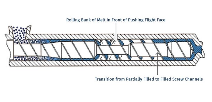
FIG 3 Single-screw devolatilizing extruder with rolling banks of polymer.
The focus on distributive mixing may seem a bit misplaced at first, but it is important to remember that as the immediate layer at the surface of the melt is depleted of the volatile components, the process shuts down unless that surface is replaced with fresh melt. The diffusion rate of volatiles in the melt relative to the short time in a DV zone is such that a high degree of mechanical mixing needs to occur, coupled with surface-area regeneration to keep the stripping process at its highest rate.
Unfortunately, options for mixing are limited, because one cannot simply put in kneading or other non-conveying elements, as that would risk material backing up into the vent. Instead, we optimize the turnover in the channel, exchange between screws in a twin-screw extruder, and the time in the devolatilization zone. Screws in typical devolatilization sections, whether single- or twin-screw, are partially filled and experience laminar flow, meaning that bringing fresh material to the surface of the rolling bank can be accomplished only through high rates of laminar mixing. Multiple flights, more steeply pitched screws, and interruptions in flights all contribute to maximizing the rate of bringing fresh material to the surface.
What is important to note is that these are all predictable parameters, without having to model bubble nucleation, growth, and rupture. One knows that surface area is important and that the rate of generation of surface area is important. Regardless of bubbles or no bubbles, nothing leaves the melt unless it is at a melt/gas interface.
For example, one can write a simple relationship for generation of surface area per unit time as a function of the number of channels, the geometry, and the screw speed. It is important to remember that the total surface area is the film deposited on the barrel wall, along with the face of the rolling bank of polymer.
These simple relationships show that the rate of surface-area generation increases with the number of channels, screw speed, and decreased degree of channel fill. The pitch of the screw, generally set as a square pitch (one turn of the flight in one diameter of the screw) can be altered to a steeper pitch to improve surface-area generation. This is embedded in the helical length of the zone Z as shown here:
SAc = (Vy) × (nZH) (surface area/unit time in channel)
SAb = (1-f)W × nZ × N (surface area/unit time on barrel surface)
W = channel width
f = fill fraction
Z = helical length of zone
N = screw speed
n = number of channels
H = channel depth
Vy = rolling-bank face velocity
Similar relationships may be developed for residence time in the zone, which contributes to both mixing and surface-area generation. It stands to reason that the longer the polymer is in the vented section, the more volatiles will be removed.
Thermodynamic Variables
The thermodynamic variables (the mere word strikes fear into the hearts of many of us) come down to maximizing the driving force for volatiles to leave the melt or solution and enter the vapor space above the melt.
While thermal energy is one of the primary drivers for devolatilization, too high a temperature for too long a time will harm the polymer in other ways, leading to oxidative degradation, etc.
The controlling thermodynamic mechanisms change as the concentration of the volatile component changes. Very high concentrations of solvent or monomer behave much like a boiling process. Here the controlling mechanism is driving heat into the melt or solution and allowing a rapid decompression. The elements of the screw design have little impact on this, other than to knock down the foam and prevent flying polymer in the vents.
Very high concentrations of solvent or monomer behave much like a boiling process.
As the concentration of volatiles diminishes, the mechanism moves to a diffusion-controlled mechanism. There is lots of discussion about superheating in the literature, and while sufficient energy must be applied to overcome the heat of vaporization etc., this is seldom the limiting step other than in the initial venting operation for a low-solids feed. Instead, the controlling mechanisms are the aforementioned surface-area generation coupled with the partial pressure of the volatilizing species.
Partial pressure is a critical variable in predicting the separation of a gas from a polymer melt. Gases will want to equalize their pressure between two phases that are open to one another. A gas will move from an area where its partial pressure is higher to an area where its partial pressure is lower. In addition, the greater the partial-pressure difference between the two areas, the more rapid is the movement of gases.
The movement from the melt to the vapor space above the melt is dictated by the solubility of the gas in the melt and the partial pressure of that component above the melt. This is the fundamental relationship spelled out in Henry’s law, which one may remember from high school or college physics. Henry’s law states that the concentration of gas in a liquid is directly proportional to the solubility and partial pressure of that gas. The greater the partial pressure of the gas, the greater the number of gas molecules that will dissolve in the liquid. The concentration of a gas in a liquid is also dependent on the solubility of the gas in the liquid.
Leaking systems, inadequate vacuum levels, or the wrong types of vacuum pumps can all dramatically reduce the performance of a vent.
The Flory-Huggins equation shows the relationship between how much of a volatile component wants to stay in the melt and the vapor pressure above the melt. While neither the Flory-Huggins equation nor Henry’s law are directly applicable to a DV vent, qualitatively they can teach a lot:
log(P1/P01) = log(1-V2) + V2 + XV22
P1 = vapor pressure above the melt
P01 = vapor pressure of pure substance at the temperature under consideration
V2 = volume of polymer in binary mixture
X = Chi or Flory-Huggins parameter
From the thermodynamics side, one simply wants to eliminate as much of the volatile component from the vapor space above the melt as possible. This translates to:
• As high a vacuum level as conditions will permit;
• Use of inert sweep gases (nitrogen) to further reduce the concentration of the stripping species above the melt;
• Put energy into the melt to compensate for cooling created by the stripping action.
One can condense all the math into some simple rules of thumb:
• Maximize surface area and regeneration of surface area.
• Ensure the highest degree of distributive mixing in the partially filled channels.
• Reduce the concentration of the volatile species above the melt by employing high vacuum levels and possible sweep gases.
• Stage the stripping (multiple vents) to reflect the changes in controlling mechanisms.
• Keep the viscosity low to minimize degradation.
• Keep oxygen out of the system to minimize degradation.
Practical Matters Matter
There are a variety of practical aspects for good devolatilization performance, including having the proper number of stages and preventing polymer buildup in vents, flying polymer, or cooling of the melt as a result of too rapid stripping action. There are several continually recurring themes for poor devolatilization. These include:
• Flying polymer: When the rate of volatile removal is high, devolatilization is more of a boiling process, generating significant amounts of foam and bubbles. As the solution decompresses, gases escape, bubbles are formed and rupture, and there is significant loss of temperature due to the cooling effects of the heat of vaporization of the volatilizing species. This often results in the foam solidifying and coming off the screws and being entrained into the venting system, with all the expected undesirable consequences. Allow sufficient screw length after the upstream seal prior to the vent opening to allow the screws to break down the foam and reheat the melt.
• Polymer backing up into the vent: This is a result of too long a filled length (or too short a pumping section) downstream of the vent prior to the downstream seal. Increase the screw speed, improve the pumping efficiency of this section (shallower screw channel), or simply increase the length of screw between the vent opening and the downstream seal. Decrease the pressure drop over the downstream seal so there is less of a ΔP to pump against.
• Thermal regeneration: Stripping large masses of volatiles will significantly cool the melt, perhaps not to the point of solidification, but certainly to the point where further volatilization is impaired. The pumping section and the melt seal downstream of a venting section can be designed to impart more viscous heating to the melt so that the subsequent devolatilization zone operates more efficiently.
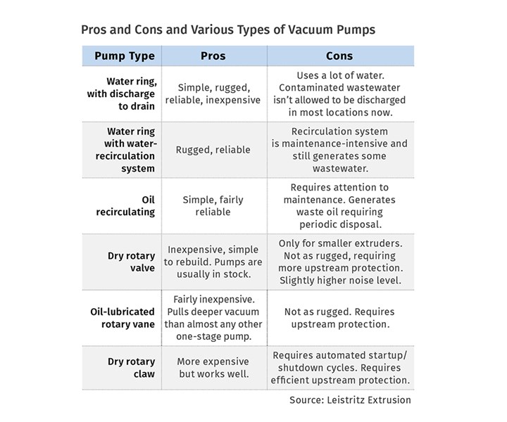
• Poor vacuum: Leaking systems, inadequate vacuum levels, or the wrong types of vacuum pumps can all dramatically reduce the performance of a vent. We focus on the extruder while often ignoring the ancillary components that are equally important to this stripping operation.
• Too much in one step: There are practical limits to the reduction in volatiles that can be accomplished in one zone. The beauty of an extruder, especially a twin-screw, is that you can stage the devolatilization vents and optimize the performance of each one. It is not realistic to expect to remove much more than an order of magnitude in concentration per vent—and not necessary, either. Stage the stripping, because it allows the greatest process flexibility and greatest turn-up and turn-down ratios for the extruder.
• Creating new volatiles: Understand the degradation mechanisms for your polymer. Be careful not to subject the melt to conditions that will cause it to unzip, as it is a battle you will not win. Avoid oxygen, and design the stripping stages so that the last vent before discharge is operating at close to capacity. This maintains a lower viscosity throughout the machine and minimizes degradation in the extruder.
ABOUT THE AUTHOR: Rob Jerman has developed twin-screw extrusion systems for devolatilization, mixing and compounding, and reactive systems for over 30 years and has significant experience in product and process development in fluoropolymers. He has his own consulting firm, Extrusion Technology and Innovations, part of Extrusion Edge. Contact robertjerman@extrusionti.com.


Related Content

How to Select the Right Tool Steel for Mold Cavities
With cavity steel or alloy selection there are many variables that can dictate the best option.
Read More
How to Get Rid of Bubbles in Injection Molding
First find out if they are the result of trapped gas or a vacuum void. Then follow these steps to get rid of them.
Read More
The Strain Rate Effect
The rate of loading for a plastic material is a key component of how we perceive its performance.
Read More
How to Stop Flash
Flashing of a part can occur for several reasons—from variations in the process or material to tooling trouble.
Read MoreRead Next
Why (and What) You Need to Dry
Other than polyolefins, almost every other polymer exhibits some level of polarity and therefore can absorb a certain amount of moisture from the atmosphere. Here’s a look at some of these materials, and what needs to be done to dry them.
Read More
Advanced Recycling: Beyond Pyrolysis
Consumer-product brand owners increasingly see advanced chemical recycling as a necessary complement to mechanical recycling if they are to meet ambitious goals for a circular economy in the next decade. Dozens of technology providers are developing new technologies to overcome the limitations of existing pyrolysis methods and to commercialize various alternative approaches to chemical recycling of plastics.
Read More
Processor Turns to AI to Help Keep Machines Humming
At captive processor McConkey, a new generation of artificial intelligence models, highlighted by ChatGPT, is helping it wade through the shortage of skilled labor and keep its production lines churning out good parts.
Read More