
The Cosmetic Process Window: Key to a No-Tweak, Robust Process
Establishing a process with the widest possible cosmetic window can help put your injection molding on cruise control.


You’ve just finished molding parts from a tool hung in the press this morning, and you have submitted first shots to the quality inspector for dimensional verification. What is the first thing that the inspector is going do? Is she going to pick up a pair of calipers and start measuring the parts right away, or is she going to first inspect the parts for any cosmetic defects? If the parts are short or if they have flash, there is no chance you are going to convince the inspector to measure the parts.
How about another scenario: You’d like to drive you car in cruise control at 80 mph for 4 hr at a stretch. Given a choice between a narrow and winding road at the edge of a cliff and a straight road with a wide lane, what would be your choice? The answer is obvious! If you choose the edge-of-the-cliff road, it’s very likely that at some point you will fall off the cliff. Even if you do manage to finish this journey, that doesn’t mean you’ll be successful during future journeys. Also important: the cliff journey is stressful. You have to pay constant attention to the road, with no room for any deviation from the settings. You can never take your eyes off the road and will have to monitor the drive constantly .


Just as driving a car 80 mph along a cliff’s edge for 5 min does not guarantee you can do it for 4 hr and all future journeys. Similarly, successfully molding 10 parts and assuming that you can then run 100,000 parts with no issues is also a myth.
In injection molding, we often find ourselves in similar situations. If the parts are short at a pack-and-hold pressure of 3750 psi (plastic) and cosmetically acceptable at 4000 psi but will flash at 4500 psi, the window to mold parts with acceptable cosmetics is very small. The window inside which cosmetically acceptable parts can be molded is defined as the Cosmetic Process Window (CPW). In this case, if the job is a week-long run of a 100,000 parts, there is a very high probability of molding short shots or parts with flash. The frequency of parts inspection will need to be higher.
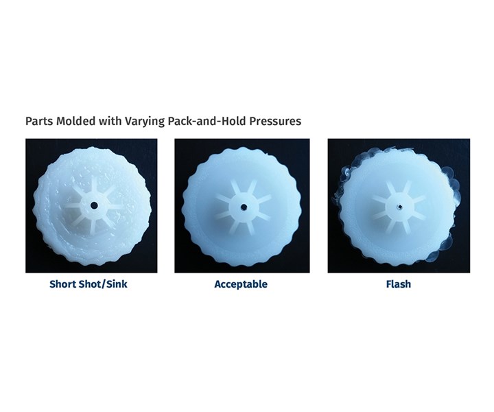 FIG 1 Parts from the same mold, molded at three different pack-and-hold pressures, yield parts that are short with sinks, parts that are cosmetically acceptable, and parts that have flash.
Unfortunately, “100% inspection” is more common than we think. Processes with smaller cosmetic windows require constant attention by process engineers, equivalent to driving a car at 80 mph at the edge of the cliff. Just as driving a car 80 mph along a cliff’s edge for 5 min does not guarantee you can do it for 4 hr and all future journeys, similarly, successfully molding 10 parts and assuming that you can then run 100,000 parts with no issues is also a myth. We have to understand short-term variation and long-term shifts. The molding process must be robust enough to capture these variations and shifts.
Figure 1 shows parts from the same tool molded at three different pack-and-hold pressures, yielding parts that are short with sink, or are cosmetically acceptable, or have flash. The pressures mentioned in this article are plastic pressure values (not hydraulic pressures). A Process Window Study was done at melt temperatures of 480 F and 520 F—the high and low recommended by the data sheet for this ABS. At 480 F, parts molded below 4000 psi yielded shorts and sinks, and parts molded above 10000 psi yielded parts with flash. Parts molded between 4000 and 10000 psi (inclusive) yielded parts that were free of sink, flash or short shots. The same study was repeated at 520 F, and the pressure limits were found to be 3000 and 9000 psi. These four data points form the Cosmetic Process Window (CPW). Parts molded within the CPW are cosmetically acceptable (Fig. 2). We are not considering dimensions when performing this study.
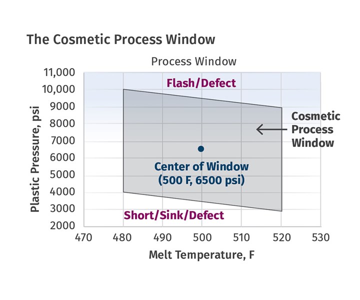 FIG 2 Process window study was done at melt temperatures of 480 F and 520 F, the high and low recommended on the plastic (ABS) data sheet. At 480 F, parts molded below 4000 psi yielded shorts and sinks, and parts molded above 10,000 psi yielded parts with flash. Parts molded between 4000 psi and 10,000 psi were free of sink, flash or short shots.
Going back to the analogy of choosing the road to drive on and looking at the CPW, it becomes clear that the choice of molding conditions would be the center of the window. In this case, that results in a melt temperature of 500 F and 6500 psi of pressure. Setting the process at these conditions and having a wide process window will ensure that the molded parts will always be cosmetically acceptable. Any natural variations and shifts around these settings will get cushioned in not requiring any tweaking by the process engineer. A wide process window is key to process robustness.
Only after this study is done should a molder look at part dimensions. Part dimensions are a function of shrinkage, which is based on the Pressure-Volume-Temperature (PVT) relationship for the given plastic. Shrinkage here is related to volume, and therefore the given volume is dependent on pressure and temperature. Therefore, pack and hold pressures and melt and/or mold temperatures are the main factors that affect the part dimensions. There are several other factors that affect the dimensions and will be discussed in a later article. The technique of Design of Experiments (DOE) is used to evaluate the dimensions. During a DOE, parts are molded at the four corners and the dimensions are plotted as contour plots inside an inscribed rectangular window.
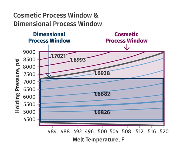 FIG 3 Molding at the center of the dimensional process window will yield a robust process. On each side of this setting there is plenty of room for variation and shift.
In Fig. 3, the diameter of the wheel considered for the CPW study is plotted from the DOE results. The nominal value is 1.685 in. with a tolerance of 0.006 in. on the lower side and 0.009 in. on the upper side. The outside box is the CPW, and the inside box that was drawn based on the green contours is the Dimensional Process Window (DPW). The solid green line is the nominal value, and clicking anywhere on the line will give the combination settings of the pack-and-hold pressure and the melt temperature to produce parts at the nominal value. For the DPW, the lows and highs for the pressure are 4250 and 7250 psi and 480 F and 520 F for the temperature. The center of the window is 5750 psi and 500 F. Molding at the center of the window will again give us a robust process, since on either side of this setting there is plenty of room for any variation and shift.
Now consider this same mold but with a hypothetically small cosmetic process window. The temperatures used and the low pressure of 4000 psi are still the same, but the mold starts to flash at 5000 psi (Fig. 4). Since the DPW is a subset of the CPW, the DPW is now very small, as far as the pressure is concerned (Fig. 5). The center would be 4500 psi, and we could mold acceptable parts for a short time, but over a week-long run—because of natural variations in the machine, material, environment (including personnel)—it is very likely that parts could be molded that are short, out of spec on the lower side, or have flash. If the parts are cosmetically acceptable but have dimensions below the lower spec limit, increasing the pressure could cause flash. We are once again driving the car on the edge of the cliff, and 100% inspection is now required.
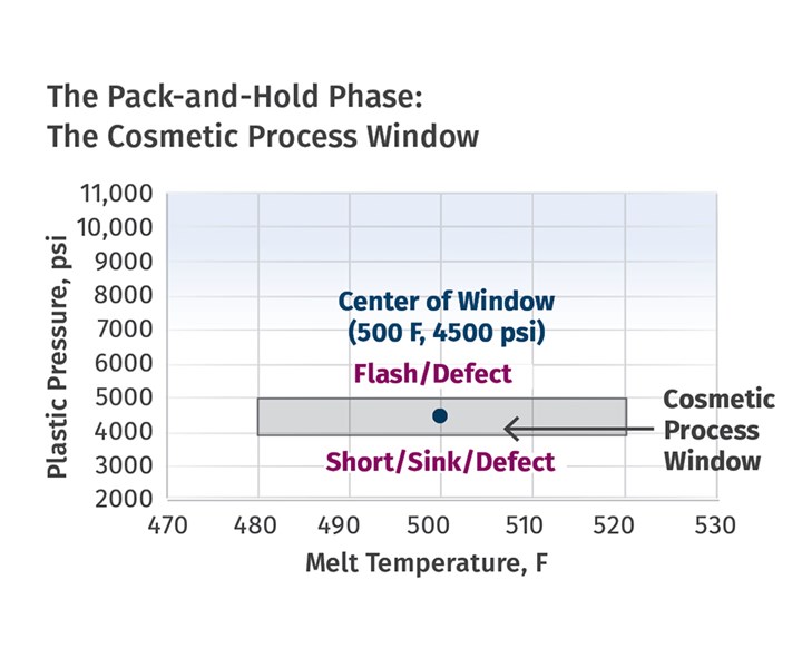 FIG 4 Parts here are molded in a hypothetically narrow cosmetic process window. The temperatures used, and the low pressure of 4000 psi are still the same, but the mold starts to flash at 5000 psi.
The discussion above therefore mandates a wide DPW for a robust process. Since the DPW is a subset of the CPW, the CPW also must be wide. The natural variation will get cushioned in a production run. Over time, the mold components will wear, the gates will wear, the vents will start getting crushed, the material lots will vary, and the part quality can shift. Results from the DOE will let you make data-driven decisions to change the process and still mold parts within the specifications.
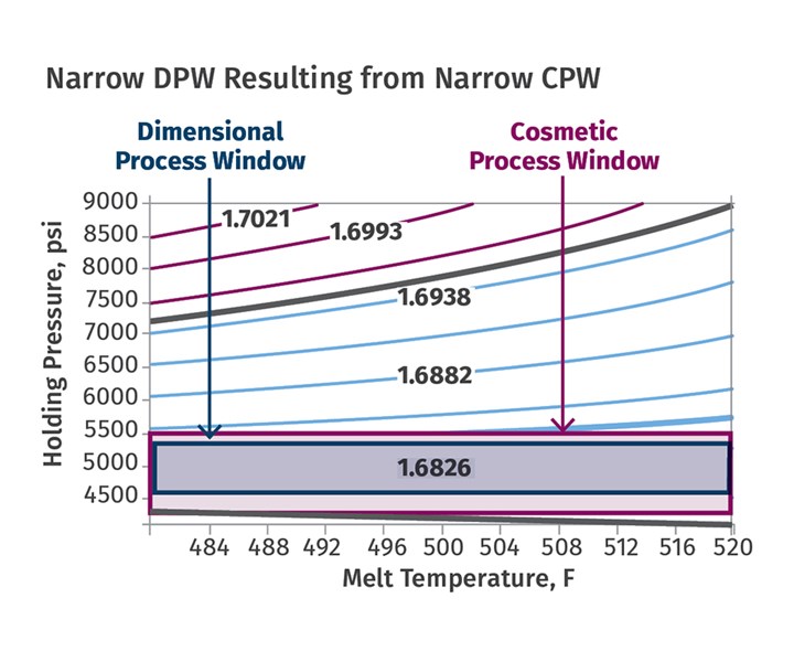 FIG 5 A narrow dimensional process window results from a narrow cosmetic process window.
It is therefore the area of the CPW that is the critical first step to achieving a robust process, zero defects, reduced inspection and no process tweaking.
ABOUT THE AUTHOR: Suhas Kulkarni is president of Fimmtech Inc., which specializes in services and training related to plastic injection molding. He earned his Masters in Plastics Engineering from the University of Massachusetts, Lowell, as well as a Bachelors in Polymer Engineering from the University of Poona, India. He has 27 years’ experience as a process engineer and is the author of Robust Process Development and Scientific Molding, published by Hanser Publications, now in its second edition. He also works as a contract faculty member at U.Mass.-Lowell. Contact: suhas@fimmtech.com; fimmtech.com.


Related Content

How Much L/D Do You Really Need?
Just like selecting the extruder size and drive combination, the L/D should be carefully evaluated.
Read More
How to Select the Right Tool Steel for Mold Cavities
With cavity steel or alloy selection there are many variables that can dictate the best option.
Read More
Are Your Sprue or Parts Sticking? Here Are Some Solutions
When a sprue or part sticks, the result of trying to unstick it is often more scratches or undercuts, making the problem worse and the fix more costly. Here’s how to set up a proper procedure for this sticky wicket.
Read More
Why (and What) You Need to Dry
Other than polyolefins, almost every other polymer exhibits some level of polarity and therefore can absorb a certain amount of moisture from the atmosphere. Here’s a look at some of these materials, and what needs to be done to dry them.
Read MoreRead Next

Process Capability and the ‘Hesitation Effect’
Understanding the concepts of pack and hold and applying them during process development is critical for molders to achieve consistent part quality.
Read More
Optimizing Pack & Hold Times for Hot-Runner & Valve-Gated Molds
Using scientific procedures will help you put an end to all that time-consuming trial and error. Part 1 of 2.
Read More
Improving Molding Process Capability: Understanding the PVT Graph, Part 1
Process capability is related to the variation in part dimensions from shot to shot. High values of process capability require the shrinkage of the material to be identical on each shot, which can be confirmed from the pressure-volume-temperature (PVT) graph.
Read More