Optimizing Pack & Hold Times for Hot-Runner & Valve-Gated Molds
Using scientific procedures will help you put an end to all that time-consuming trial and error. Part 1 of 2.
In a majority of tools, molders use only one phase after the injection phase to pack and hold the plastic in the mold—the so-called hold phase. In reality, the molder must differentiate between the pack and the hold phases. For the sake of simplicity, in this article, we’ll refer to the second phase as the hold phase and cover the technique of optimization, and then further differentiate the two in the second part of this series in December.
For cold-runner molds, hold times are optimized by conducting a gate-freeze study where the part weight is recorded as a function of the hold times. When the gate freezes, the part weight remains constant with increasing time. A second or so is added to the lowest value of time where the part weight stays constant, and this number is taken as the total time for the setting of hold time.
In hot-runner or valve-gated systems, on the other hand, the gate area always has molten plastic, and therefore the part-weight curve never flattens. As a result, the above method does not produce acceptable results.
Molders need to find an optimized combination of hold times and pressures, and then conduct a DOE to optimize the parameters within the available limits.
Excessive hold time and hold pressure can cause defects such as flash, stress in the part, and parts staying on the wrong side of the mold. Inadequate pressure, however, can cause shorts, sinks, and dimensional issues. Molders need to find an optimized combination of hold times and pressures, and then conduct a DOE (Design of Experiments) to optimize the parameters within the available limits.
Two other terms need explanation. The first is the Cosmetic Process Window (CPW) and the second is Dimensional Process Window (DPW). CPW refers to the process limits within which cosmetically acceptable parts can be molded. DPW reflects the process limits within which parts can be molded so that they are dimensionally acceptable. The DPW is always inside the CPW.
What follows is the procedure to optimize hold times for hot-runner and valve-gated molds. It is based on a two-cavity screen mold used to make parts for the irrigation industry.
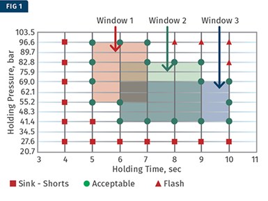
Red squares represent a part with a defect at lower pressures and times; red triangles indicate a part with a defect on the higher end of the pressures and times; and green circles show a part that is cosmetically acceptable.
First, a template to generate a cosmetic process window was prepared. The X-axis corresponds to the holding time and the Y-axis corresponds to the holding pressure. Such a template is called a Visual Inspection Template (VIT). A completed VIT is shown in Fig. 1. The red squares represent a part with a defect at lower pressures and times (sink, short shot, etc.); red triangles show a part with a defect on the higher end of the pressures and times (flash, overpacked parts, etc.); and green circles reveal a part that is cosmetically acceptable.
Starting with a hold pressure of 27.6 bar (400 psi), parts were molded from 27.6 bar to 96.6 bar (1400 psi) in steps of 13.8 bar (200 psi) with holding times from 4 to 10 sec in 1-sec increments. The data was collected and recorded in the VIT. The defect at the lower pressures and times was sink, while on the higher side, it was flash in the screen area. One can now draw several CPWs in the VIT.
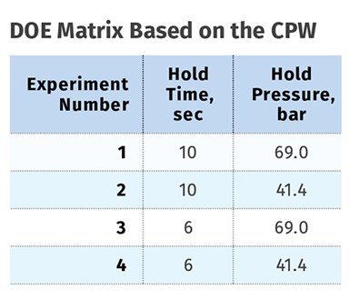
Once these windows are determined, the next step is to look for dimensions using the DOE technique. The process is varied between the limits of the windows and the dimensions that are evaluated. After considering the three CPWs and other production requirements, it was decided to pick Window 3 for determining the limits of the DOE. The DOE matrix is shown in the accompanying table.
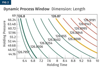
Parts were molded at the four settings indicated in the table and were measured for dimensions. The dimensional requirement on this part was the length, which was specified at 126.80 ±0.07 mm. The analysis was carried out with the DOE module of the Nautilus Software. The results are shown in Figs. 2 through 4.
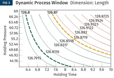
Figures 2 and 3 show the DPW for cavity one and two, respectively. The solid green contour lines represent cavity one and the dotted contour lines represent cavity two. The green lines represent the settings where the parts are dimensionally acceptable, and the red lines represent the settings where the parts are dimensionally not acceptable. The orange lines are the upper specification limits.
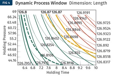
In Figs. 2 & 3 above, the solid green contour lines represent cavity one and the dotted contour lines cavity two. Green lines represent settings where the parts are dimensionally acceptable, and red lines indicate settings where parts are dimensionally unacceptable. Orange lines are the upper spec limits. Here, the two contour plots are overlayed in a combined contour graph. The area where the green contours for each cavity intersect represents settings where both cavities can be molded with acceptable dimensions.
Since there are two cavities here, the two contour plots must be overlaid to determine a combined contour graph as shown in Fig. 4. The area where the green contours for each cavity intersect represents the settings where both cavities can be molded with acceptable dimensions.
Now you can draw a composite DPW inside which the parts will be dimensionally acceptable. Such a window is shown in Fig. 5 for the above experimental data. Observing the window, notice that varying the holding time from 6.2 to 7.5 sec at 43.5 to 63.5 bar will produce dimensionally acceptable parts. Naturally, the bigger this window, the more robust the process is going to be.
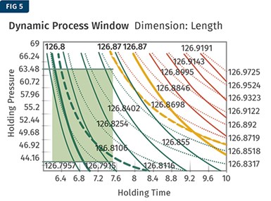
This is a composite DPW, inside which the parts will be dimensionally acceptable. Notice that varying the holding time from 6.2 to 7.5 sec between 43.5 to 63.5 bar will produce dimensionally acceptable parts.
Process robustness is the goal of every molder, so it’s best that the center of the DPW in Fig. 5 is used for the process settings. A holding pressure of 55 bar and a holding time of 7 sec were chosen as the process settings. Varying the holding time from 6.2 to 7.5 sec between 43.5 to 63.5 bar will still produce dimensionally acceptable parts. This is an indication of a robust process and will therefore produce parts not only to specifications but also with improved statistical process capability. Again, several DPWs are possible here. On molding machines, the extent of pressure variation is higher than time variation, and therefore maximizing the pressure window is always preferred.
The above mold had gone through an iteration for steel adjustment, resulting in an acceptable process window. During the first iteration, the mold could not make parts consistently to dimensional specification. The CPW was large, but the DPW was extremely small. Considering both cavities, the molding process was not robust. Remember that molding parts to spec does not mean that all the parts will be within spec; molders need to understand and measure the combined variation in the machine, material, process, and so on.
This procedure applies to hot-runner molds but can be easily extended to valve-gated molds. The procedure, in fact, is slightly simpler since the valve pin shuts off the gate, eliminating the true hold phase from the original discussion of the pack-and-hold phase. There are other parameters that also must be considered for the DOE. To keep matters simple, only two factors and one dimension were considered. Composite dimensional windows for multi-dimensions and cavities must be considered.
Optimization of holding-pressure times for hot-runner molds has always been an area of trial and error.
Optimization of holding-pressure times for hot-runner molds has always been an area of trial and error. The procedure described above is a scientific way to determine the holding pressure and time in case of hot runners and valve-gated systems. The procedure also evaluates and demonstrates the robustness of the process and the ability to mold parts consistently.
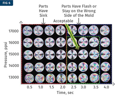
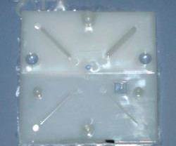
Polarized light under an optical cover revealed a sink in the gate area. A VIT was generated using these pictures, followed by a DOE.
An interesting study was done using polarized light on an optical cover (see Fig. 6). In this case, the sink in the gate area was visible under polarized light. A VIT was generated using these pictures followed by a DOE as described above.
Next issue, the focus will be on differentiating between the pack and hold phases for both hot and cold runners.
ABOUT THE AUTHOR: Suhas Kulkarni is the founder and president of Fimmtech, San Diego, an injection molding service-oriented firm focusing on Scientific Molding. Fimmtech has developed several custom tools that help molders develop robust processes, and its seminars have trained hundreds of individuals. Kulkarni is an author of the best-selling book, Robust Process Development and Scientific Molding, published by Hanser Publications. Contact: (760) 525–9053; suhas@fimmtech.com; fimmtech.com.
Related Content
The Effects of Temperature
The polymers we work with follow the same principles as the body: the hotter the environment becomes, the less performance we can expect.
Read MoreHow to Select the Right Tool Steel for Mold Cavities
With cavity steel or alloy selection there are many variables that can dictate the best option.
Read MoreHow to Stop Flash
Flashing of a part can occur for several reasons—from variations in the process or material to tooling trouble.
Read MoreUnderstanding Strain-Rate Sensitivity In Polymers
Material behavior is fundamentally determined by the equivalence of time and temperature. But that principle tends to be lost on processors and designers. Here’s some guidance.
Read MoreRead Next
Processor Turns to AI to Help Keep Machines Humming
At captive processor McConkey, a new generation of artificial intelligence models, highlighted by ChatGPT, is helping it wade through the shortage of skilled labor and keep its production lines churning out good parts.
Read MoreTroubleshooting Screw and Barrel Wear in Extrusion
Extruder screws and barrels will wear over time. If you are seeing a reduction in specific rate and higher discharge temperatures, wear is the likely culprit.
Read MoreHow Polymer Melts in Single-Screw Extruders
Understanding how polymer melts in a single-screw extruder could help you optimize your screw design to eliminate defect-causing solid polymer fragments.
Read More


.png;maxWidth=300;quality=90)
