
Block Cavities and Keep Molding
It goes against conventional wisdom, but molding with blocked cavities can be done while maintaining quality with the help of appropriate in-cavity sensors and process-control software.
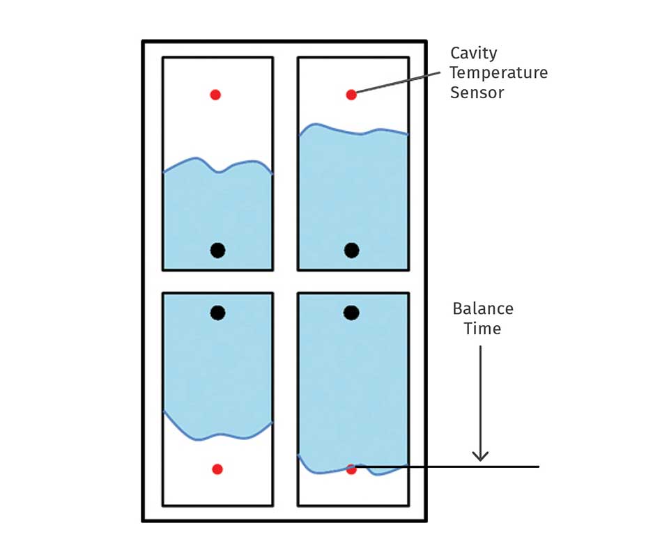
An automatic hot-runner balancing system measures the time for the melt front to reach a temperature sensor in each cavity—the balance time—and automatically adjusts the tip temperatures.
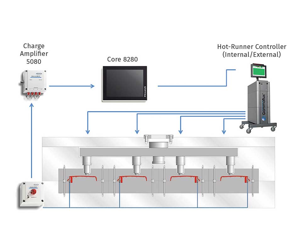
The automatic hot-runner balancing system adjusts the tip temperatures after every single shot, based on cavity-temperature sensors. Software options like adjusting the temperature every second shot, etc. are also available if needed.
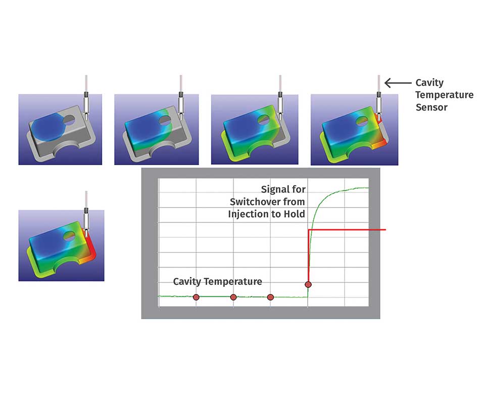
As soon as the melt front reaches the cavity-temperature sensor, a signal for switching from injection phase to holding- pressure phase is sent to the injection machine. That signal can also be delayed if the sensor cannot be placed in the ideal location because of the presence of an ejector pin or cooling line.
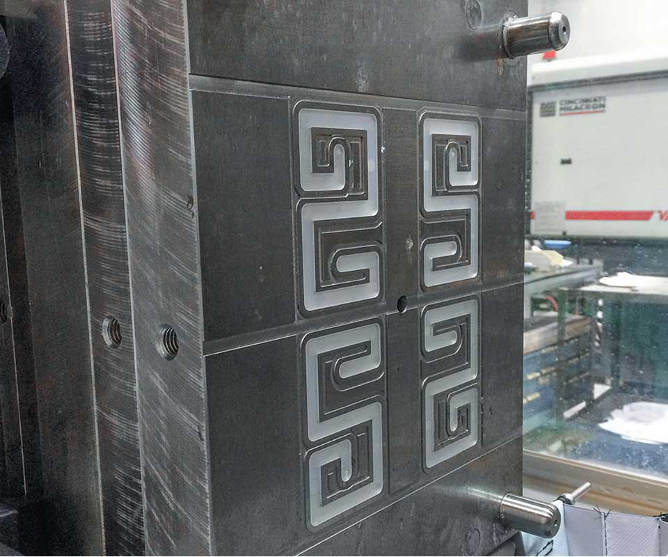
A four-cavity, direct valve-gated mold was used for the trials with blocked cavities.
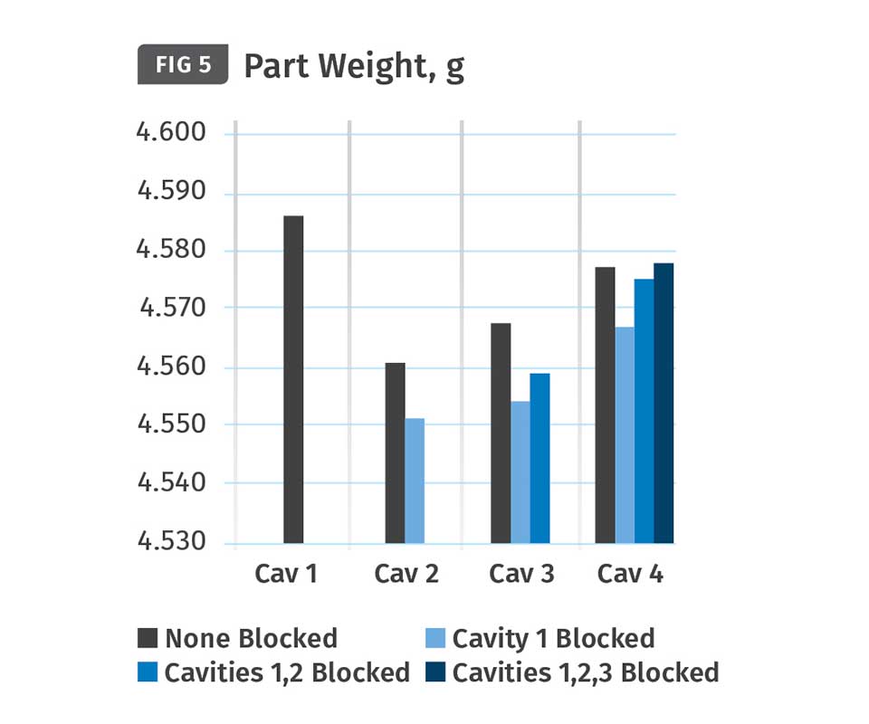
Results from blocking cavities without applying a shear-rate controller. The weight differences between the parts from the different cavities are bigger than the weight differences of the parts from the same cavities when using different numbers of open cavities.
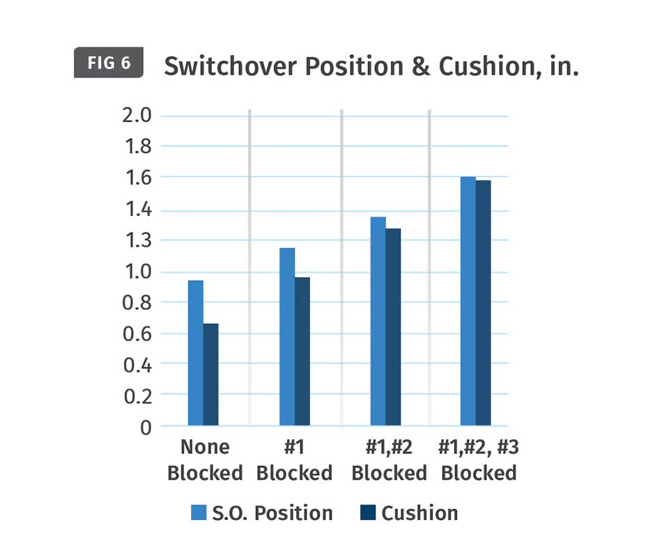
Blocking cavities without use of a shear-rate controller produces an earlier switchover position and larger cushion, because less melt is needed to fill the remaining open cavities.
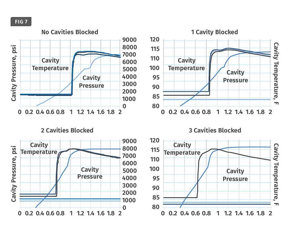
Effect of blocking cavities without use of a shear-rate controller: Cavity-temperature curves show shorter balance time and cavity-pressure curves become more steep.
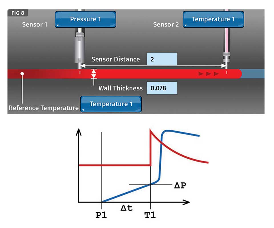
Shear-rate control involves measuring shear rate and shear stress in the cavity by means of pressure and temperature sensors.
Results from blocking cavities while applying a shear-rate controller show that the balance time remains fairly constant—around 1.1 sec—and the pressure curves remain about the same, tool.
With the use of a shear-rate controller, weight differences between cavities are smaller than before, as are weight differences in the same cavity with different numbers of blocked cavities.


We have all heard it before: You should not run your multi-cavity hot-runner molds with some nozzles blocked. But everyone who has spent some time on the shop floor of an injection molding facility knows that it’s done once in a while. The nozzles could be blocked by a foreign object in the nozzle tip; or you turned off the nozzle heater because you wanted to block the cavity because there is a broken pin or scratch in the cavity, or the nozzle was leaking, etc.
So why have we been told not to block some cavities and keep running the mold? The first problem is that the remaining cavities are not balanced anymore. That means some cavities are filled sooner than others, which consequently results in some cavities being already in the packing and holding stage while other cavities are still being filled. This leads to different packing levels in the different cavities, which results in different part weights, shrinkage, and dimensions. In the worst case, it leads to short shots or flashing.
AN AUTOMATIC SOLUTION
Balancing the remaining unblocked cavities can be very challenging, especially with a high-cavitation mold. With a self- adjusting cavity-balancing control system, this process can be automated. Instead of the operator looking at the parts and adjusting the tip temperatures, cavity-temperature sensors are installed in each cavity of the mold to measure the time from injection start until the melt front has reached the sensors (see Fig. 1). This time is called the balance time and is measured down to the millisecond. The balance times for all the cavities are then compared by the software and an algorithm calculates which nozzle temperature must be increased or decreased and by how much. This information is transferred to the hot-runner controller after the end of each cycle. The hot-runner controller then adjusts the tip temperatures automatically, which provides a totally balanced mold (Fig. 2).
The second problem is that the shot size or the switchover position for switching from injection phase to the holding-pressure phase has to be adjusted because the number of the cavities being filled has been reduced. After blocking one or more cavities, a disciplined technician will make another short- shot study to determine the new switchover position or new value for the shot size. If the technician is a bit less disciplined, a rough guess will be made and the new value for one of the parameters mentioned will be set. As long as there is no short shot or flash, the technician might be satisfied, restart the production, and move on to the next machine that requires his attention. This procedure is not scientific at all and can lead to dimensions out of specification or material waste as too much plastic gets pushed into the cavities.
The right thing to do is to apply the automatic switchover process from injection stage to holding phase by means of melt-front detection with a cavity-temperature sensor. By applying this process, the screw position after plasticating has no influence on the switchover position of the screw when switching from injection to holding stage. As soon as the melt front hits the cavity-temperature sensor, the software detects the rise of the cavity-temperature curve and sends a signal to the injection machine to
switch over to holding stage. Switchover to holding stage is normally suggested to be done when the cavities are about 97% full.
The position of the temperature sensors is probably never exactly where you want it to be because of the presence of an ejector pin or cooling line. However, the control software (such as Priamus FillControl) can easily allow delaying the switchover signal to the injection machine by any amount down to a millisecond after the first melt front reaches a temperature sensor. So long as the injection machine is able to switch over to holding stage before the melt front reaches the end of fill, you are safe (Fig. 3).
AN ‘EXTREME’ EXAMPLE
To illustrate the procedure using these control techniques, a trial was conducted at our sister company, Synventive Molding Solutions, in its lab in Peabody, Mass., using a four-cavity direct valve-gated mold (Fig. 4). In the first set of trials, automatic hot-runner balancing and switchover from injection to holding stage was achieved by melt-front detection with a cavity-temperature sensor. First one cavity was blocked, then two cavities, and finally three cavities of the four-cavity mold. Blocking three of four cavities means 75% of the cavities were blocked, which is quite extreme but will prove the concept.
The results in Fig. 5 show that the weight differences between the parts from the different cavities are bigger than the weight differences of the parts from the same cavities when using different numbers of open cavities. This is exactly what you want to achieve— the weight of the parts is basically independent from the number of cavities you are using.
As seen in Fig. 6, the switchover position from injection stage to holding stage is traveling backwards to higher cushion values when fewer and fewer cavities are open and less material needs to be injected. It is also clearly recognizable that the difference between switchover position and cushion is getting smaller as more cavities are blocked. That observation makes sense because the fewer the cavities that are getting filled, the less plastic that has to be delivered to compensate for shrinkage in the unblocked cavities. It appears that the weight of the parts is independent of the number of cavities used, but the shear rate in the cavities is changing, which might influence the quality of the parts. For example, if processing materials with a high glass content, the glass fibers get more aligned at a higher shear rate than if processed at a lower shear rate. A higher shear rate means the flow-front velocity is higher, which will produce parts with a more shiny surface when using highly glass-filled materials. Figure 7 shows the cavity-pressure and cavity-temperature curves of the filling phase with all the cavities open, one cavity blocked, two cavities blocked and finally three cavities blocked.
It can be recognized that the balance time (time from injection start until the melt front reaches the cavity-temperature sensor) is getting shorter as more cavities get blocked and the plastic volume flow coming from the barrel of the injection machine stays the same. From an injection molding point of view, this balance time is very similar to the fill time, depending on the location of the temperature senstors in the cavities. The cavity-temperature sensors in the blocked cavities are measuring the cavity temperatures only, as no melt reaches the sensors since the cavities are blocked. In addition, it can be observed taht the slope of the cavity pressure curves get steeper as more cavities are blocked. The reason for that is the increasing melt-front velocity.
SHEAR-RATE CONTROL
The effect of the shear rate changing according to the number of cavities blocked can be eliminated with a shear-rate controller. The basics of such a controller start with measuring the shear rate in the cavity. The shear rate in this case can also be correlated with the melt-front velocity or the time between the melt front reaching two cavity sensors. Usually the first sensor that gets reached by the melt front is a cavity-pressure sensor, typically located near the gate. A cavity-pressure sensor in this position provides the additional benefit of measuring the shear stress and with that, the viscosity in the cavity, as well (Fig. 8). The second cavity sensor is normally a cavity-temperature sensor as it is less expensive than a cavity-pressure ssensor, and only the time when the melt reaches the sensor is of interest in this case.
The shear rate or melt-front velocity in the cavity is directly linked to the injection speed of the molding machine. So by using a shear-rate controller (such as Priamus FillControl Control P software), one is automatically controlling the injection speed of the molding machine. During every cycle, the shear rate is measured in the cavity and compared with the set value, and if there is a difference, a new value for the injection speed is sent to the controller of the injection machine.
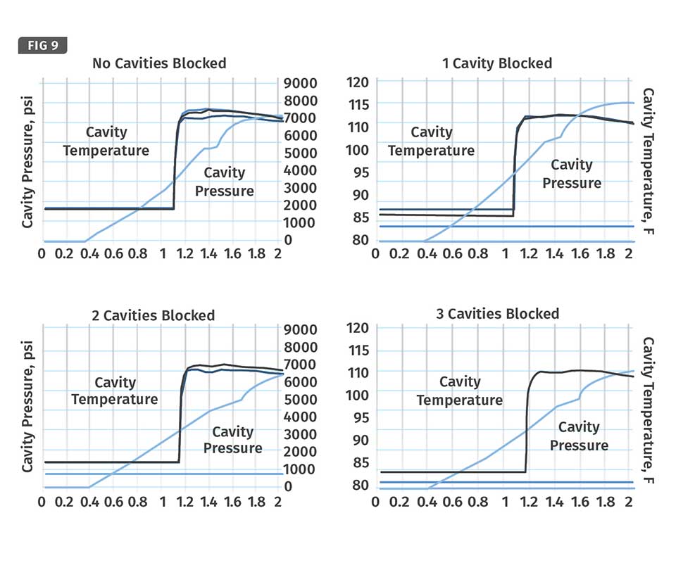
When applying the shear-rate controller in our trial, it can be seen that the balance time stays consistently at about 1100 millisec (Fig. 9). This means the shear rate and flow-front velocity stay the same, regardless of the number of cavities blocked. Also, the slope of the cavity pressure curves stays the same.
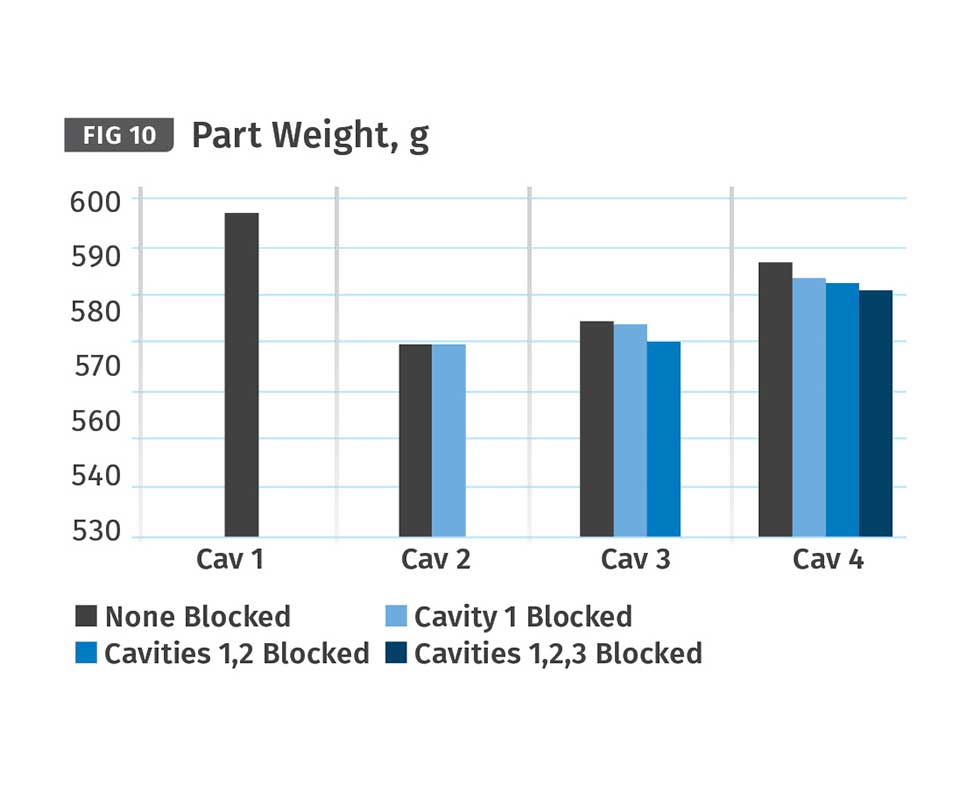
After reviewing the weight of the parts made while applying the shear-rate controller (Fig. 10), it is apparent that the differences between the weights in the same cavity got even smaller when blocking one, two, or three cavities. Again, the switchover position and cushion will increase as more cavities are blocked (Fig. 11). So by using shear-rate control it was possible to achieve not only a consistent shear rate and melt-front velocity, but also an even smaller difference of the part weights independent of the number of cavities blocked.
Figure 12 shows the differences in balance times depending on the number of cavities blocked, with and without applying shear-rate control.
CONTROLLING PEAK CAVITY PRESSURE
For some applications, one would like to make sure that the peak cavity pressure stays at a specific value. This could be the case, for example, if a specific pressure needs to be achieved in an optical part to make sure the optical characteristics do not change. This can be done with a compression controller.
For example the Priamus FillControl Control P software also includes a compression controller. The software measures the peak cavity pressure in each cycle and compares it with the set value. If there is a difference between set and measured values, the software calculates the new holding-pressure value and sends that information to the controller of the injection machine. The injection machine then changes its holding pressure automatically. Communication between the process-control system and the injection machine is done through the host-computer interface of the injection machine. This is a real-world application of Industry 4.0.
Of course, molding with blocked cavities should not be done forever, as productivity goes down in the long run. But it might be good to have this capability to keep the promised delivery date for the parts to be produced, especially if that point is just a few hours away. For more troublesome molds, productivity can even go up in the long run if the mold travels less often to the mold shop and back. And with cavity-temperature sensors in the mold, one gets additional benefits, like real-time cavity-temperature monitoring and balance-time monitoring, the first of which can warn of wrong tool temperatures or blocked cooling lines, and the second detects resulting changes in the viscosity of the injected melt.
Cavities should not be blocked when processing materials that are very sensitive to the residence time in the barrel and hot runner, as the material in the nozzle that got switched off will still get some heat over time. Check with your hot-runner manufacturer whether blocking cavities is acceptable for your equipment. If it is, you now have a way to block cavities and keep molding—in a controlled way.
ABOUT THE AUTHOR: Marcel Fenner is technical manager and president of Priamus System Technologies, LLC in Brunswick, Ohio. He started his career as an apprentice plastics technician specializing in injection molding. He later worked as a process engineer and set up a department for mold trials and process development for a Swiss company specialized in insert molding. In 2000 he set up a production facility for that company in Tennessee to supply the automotive industry in the NAFTA region. He also worked for nylon resin supplier EMS-Grivory. Fenner started with Priamus in 2013 in Switzerland as technical manager and joined its North American subsidiary later that year. He was appointed president of that operation in June 2014.


Related Content

A Simpler Way to Calculate Shot Size vs. Barrel Capacity
Let’s take another look at this seemingly dull but oh-so-crucial topic.
Read More
How to Get Rid of Bubbles in Injection Molding
First find out if they are the result of trapped gas or a vacuum void. Then follow these steps to get rid of them.
Read More
Formulating LLDPE/LDPE Blends For Abuse–Resistant Blown Film
A new study shows how the type and amount of LDPE in blends with LLDPE affect the processing and strength/toughness properties of blown film. Data are shown for both LDPE-rich and LLDPE-rich blends.
Read More
Know Your Options in Injection Machine Nozzles
Improvements in nozzle design in recent years overcome some of the limitations of previous filter, mixing, and shut-off nozzles.
Read MoreRead Next

Troubleshooting Screw and Barrel Wear in Extrusion
Extruder screws and barrels will wear over time. If you are seeing a reduction in specific rate and higher discharge temperatures, wear is the likely culprit.
Read More
Processor Turns to AI to Help Keep Machines Humming
At captive processor McConkey, a new generation of artificial intelligence models, highlighted by ChatGPT, is helping it wade through the shortage of skilled labor and keep its production lines churning out good parts.
Read More
Understanding Melting in Single-Screw Extruders
You can better visualize the melting process by “flipping” the observation point so that the barrel appears to be turning clockwise around a stationary screw.
Read More