
Gating Revisited
An overlooked factor in injection molding has outsize influence on the process and part quality.
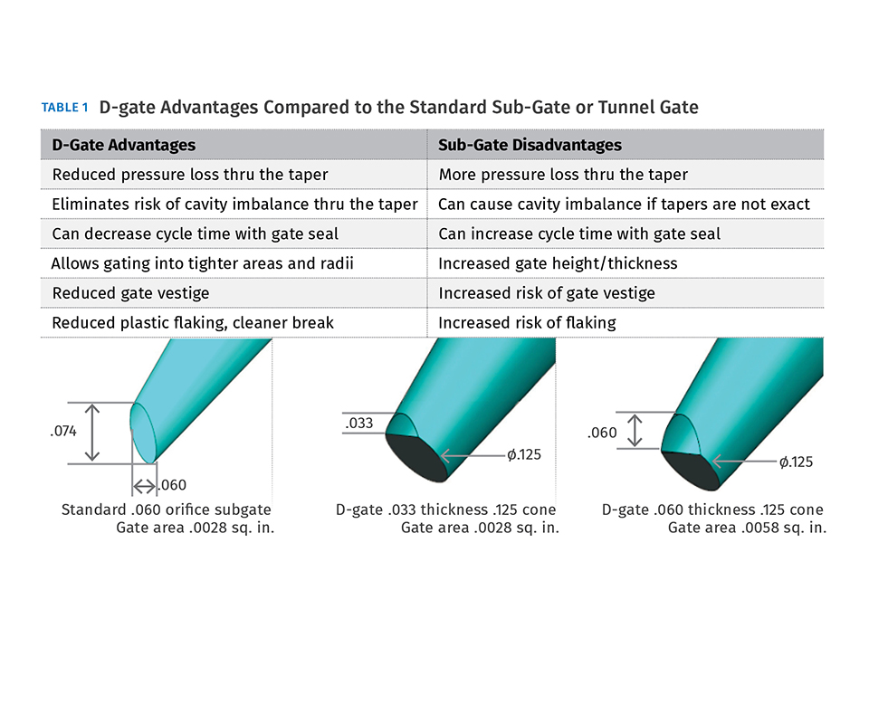
Table 1
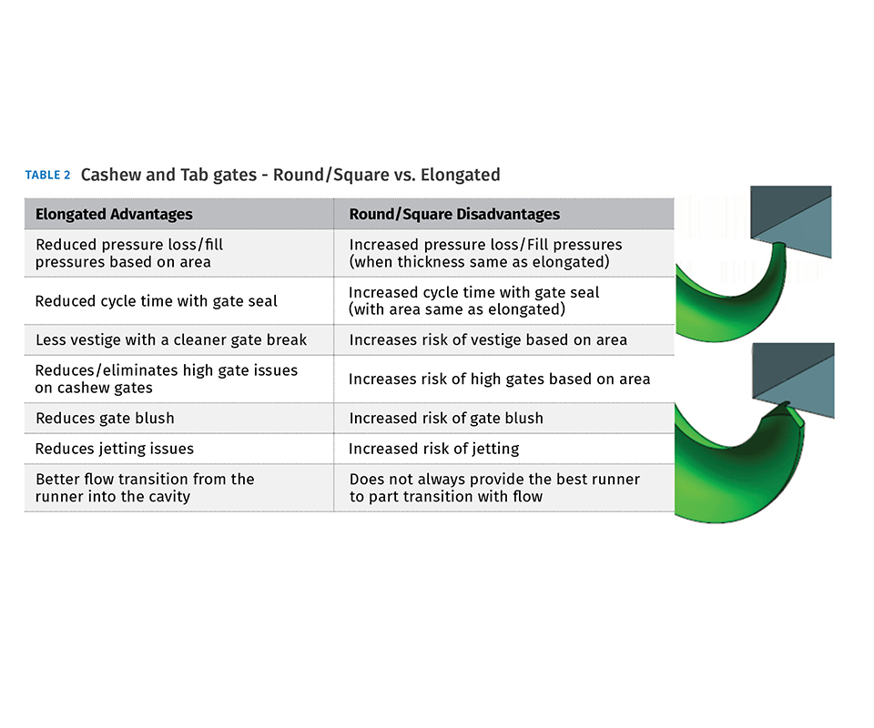
Table 2


I want to draw attention to a topic I feel the industry has not given enough attention to: the most restrictive point in the flow path of the plastic in the injection process—the gate. This area, along with runners, has been a passion of mine. I am still gathering some information on runners and their impact, but this article will focus on gating. I wrote an article for this column on “The importance of Gate Geometry” exactly two years ago (Dec. ’14) to bring some attention to this critical area in the flow of plastic to the part. I feel that gates in general are still overlooked, along with the impact they can have on the process and part quality. So I wanted to revisit this topic in more depth.
Gating and its geometry or open area can have a big impact on shear rates, gate seal, pressures, and quality issues. It still amazes me that there is not much information in the plastics industry on the impact of gating on the overall process. Most molders and moldmakers have their own opinion on gate sizing and many do not keep an open mind on the impact gate size can have on the process and part quality.
To establish gate standards you have to consider material variation, part wall thickness, and flow lengths. As I discussed in my first article on gating, I tend to err on the small side, going thin and wide when possible; but with some materials, such as glass-filled nylon, I tend to go much larger, especially with larger parts where there’s more volume of plastic to move.
Most of the efforts I have observed in the industry to control the injection process involve measuring and controlling injection pressure. This is, of course, a very critical parameter to control and to confirm you have a quality part. But I also feel the measurement of actual injection volume through the gate, and how it relates to injection pressure, would be a great tool for process analysis. The gate is typically not a big focus unless there are pressure-loss issues. Pressure-drop studies are the common means to observe the gate’s impact on the process. A recent article I read indicated that pressure-drop studies and the data they present are actually flawed. (The article, “Questioning the Science in Injection Molding: What are you actually getting in a ‘Pressure-Loss Study’?” was written by John Beaumont).
I want to bring up a couple of case studies to illustrate how the gate itself has impacts many do not consider or have not studied. A while back, before I started to find that reliance on pressure-drop studies was insufficient, I was involved with a part and process that was pressure limited at 24,000 psi, which was the maximum machine pressure available. This was a polypropylene part that had two gates and excessive flow length. The pressure-drop study showed that through the gates we had 9000 psi pressure drop, and the rest was generated through the cavity. This specific grade of PP had a high viscosity, which contributed to the process being pressure limited. (Running a standard PP required a plastic pressure of only 9000 psi.)
Some people would have suggested using a higher-pressure machine. I thought I could bring the pressure down slightly with a larger gate size but didn’t think I would be able to eliminate the pressure-limited issue. The gates were originally 0.020 x 0.080 in. and I opened them up to 0.030 x 0.080 in. We then did a pressure-drop study through the new gates, and there was no change, it was still at 9000 psi, which I found a little surprising. I then opened the gates to 0.040 x 0.080 in. and the pressure-drop study still showed 9000 psi pressure loss through the gates.
Looking back, I see it was not logical to expect this to change much, because we were just shooting a minimal amount of material through the gates, and no matter how big they were we wouldn’t see the impact without putting more volume through the gate. We then shot the whole part, and to our amazement the overall pressure drop was now down to 17,000 psi, despite the pressure-drop study still showing the same 9000-psi pressure loss through the gate. Enlarging the gates increased the volume of material that could move through the gate in the same amount of time, allowing the cavity to fill easier.
Most would assume that the first enlargement of the gates from 0.020 x 0.080 in. to 0.030 x 0.080 in. was a 50% increase in gate area, and would allow a comparable increase in flow volume per unit time. But you could also argue this was an even greater increase in effective flow orifice. I have no idea of how thick the skinning of plastic around the gate would be, but let’s suggest 0.005 in. per side. This may be a stretch, but I just want to paint a picture. If we had skinning of 0.005 in. per side at the original 0.020-in. gate thickness, the remaining flow-channel thickness would be 0.010 in. With the new 0.030-in. gate size, the flow channel would be 0.020 in., a 100% increase in effective area and potential flow volume. With this theory, going to 0.040 x 0.080 in. gate size would leave a flow-channel thickness of 0.030 in., an increase of 200% over the original size.
One other part running glass-filled nylon had a process that was also pressure limited at 24,000 psi. Based on the pressure-drop study showing relatively little pressure loss through the runners and gates, it was assumed not much could be done to remedy the situation. This tool had four cavities and a hot runner with two hot drops, each feeding a cold runner and one gate to each cavity. The parts in this case a fair amount of flow length, which also pointed to the pressure loss being in the cavity as the study suggested. The process was pressure limited when the part was 50-60% full and was not able to bury all the glass on the part at the end of fill. The gates were 0.080 x 0.125 in. and we opened them up to 0.187 x .080 in. We saw avery slight improvement but the part was still pressure limited at 80% full.
My focus then went to the hot-drop orifices, which were at 0.080 in. or 2 mm. We opened them up to 0.14 in. (3.5 mm) and our pressure drop subsided to 16,500 psi. Again, this approach increased the volume of plastic to the part and ignored what the pressure- drop study was suggesting. Both of these cases were eye-opening and cast new light on what education in the plastic industry has taught for years, and the lack of attention to the influence of gates or hot-drop orifices. In some cases, it just comes down to reducing the restriction and increasing the volume of material flow, and not always thinking about the psi pressure drop.
These two case studies are just one area of focus, and you really need to keep an open mind about when you need larger gates and when you need smaller gates. Like I mentioned earlier, I typically reduce gate sizes to eliminate other defects and molded-in stress, in some cases also reducing gate-seal time and warpage. Please reference my Dec. ’14 article on gate geometry.
Many people tend to focus on runner size as much as gate size. While I agree that the runner should always be a consideration, from my experience 99% of the time the problem is not the runner but the gate or hot-drop orifice. It depends on the length of the runner; if the runner is short, I really don’t care if it’s round or square, because it has no impact on the pressure loss unless it is extremely undersized.
MORE ON FLOW VOLUME VS. PRESSURE
My background is in moldmaking and repair. I am not a processor and have not been educated to be one. But the case studies I have mentioned are examples of how I came to the perception that flow volume through the gate—something not generally focused on by molders—can have a drastic impact on the process; and the measurement of injection pressure—which molders do focus on—does not always show the impact. I will try to paint a mental picture to help you visualize how flow volume can impact the process.
Let’s use hydraulic-cylinder size as an example. A 1.0-in.-diam. bore in that cylinder has 0.785 in.2 of surface area. A cylinder with 2-in.-diam. bore has 3.14 in.2 of surface area in the bore, which is 300% more area than the 1-in. bore. If the hydraulic pressure being used was 1000 psi, the overall force would also be 300% greater, at 785 lb of force with the 1-in. bore vs. 3140 lbf with the 2-in. bore. But even though the amount of force is 4X greater, along with 4X the volume, the pressure per square inch is still the same at 1000 psi. If the cylinder bore were instead the gate size or area, the increase in potential volume flow and force into the part would also be 400% and the measurement of injection pressure would show no increase when in actuality the volume flow and process have drastically changed.
Let’s use some realistic gate sizes and volume changes. Going from a 0.020 x 0.080 in. gate to a 0.040 x 0.080 gate has at minimum a 100% increase in potential volume flow and force. And going from a 0.050-in.-diam. to a 0.100-in.-diam. gate has an increase of at least 250% in potential volume and force.
Again, this consideration of gate area and volume is important mainly when there is an issue with a pressure-limited ability to fill or to pack the part adequately. Our current methods using pressure-drop studies focus on one parameter, and assumptions of what is relevant can blind us to the reality of what is happening inside the mold. My conversations with numerous processing technicians in the industry do confirm that there is not complete understanding of the overall impact of flow volume and cross-sectional area at the most restrictive point in the melt path.
Some will suggest I am taking this gate thing a little too far. Molders using the decades-old gate standards have robust processes, produce quality parts, and make money. This is true, but as the industry evolves and is looking for ways to become more efficient with even more robust process windows and improved quality, we have to dig where no one has dug before. Until the industry researches and studies gating along with the all the variables of the plastic, machine, and part geometry, and creates a baseline standard for gate area and geometry, it should be questioned. The only suggested gate standards I have seen are percentages of part wall thickness, but I have found these standards cannot be relied on in many cases to resolve issues. I am always looking into that 20% of cases that cause 80% of the problems, which is where attention to gating can have a big impact.
ABOUT THE AUTHOR: Randy Kerkstra has been in the plastics industry for more than 26 years, occupied frequently with troubleshooting injection molding. He is currently a tooling manager for a large, multi-plant molding and manufacturing company. Contact: kbmoldingsolutions@gmail.com.


Related Content

Polyethylene Fundamentals – Part 4: Failed HDPE Case Study
Injection molders of small fuel tanks learned the hard way that a very small difference in density — 0.6% — could make a large difference in PE stress-crack resistance.
Read More
Optimizing Pack & Hold Times for Hot-Runner & Valve-Gated Molds
Using scientific procedures will help you put an end to all that time-consuming trial and error. Part 1 of 2.
Read More
What to Know About Your Materials When Choosing a Feeder
Feeder performance is crucial to operating extrusion and compounding lines. And consistent, reliable feeding depends in large part on selecting a feeder compatible with the materials and additives you intend to process. Follow these tips to analyze your feeder requirements.
Read More
Fundamentals of Polyethylene – Part 3: Field Failures
Polyethylene parts can fail when an inappropriate density is selected. Let’s look at some examples and examine what happened and why.
Read MoreRead Next

Two-Shot Molding and Tool Design
There are a few variations of the two-shot molding process, and each has implications for tool design.
Read More
The Importance of Gate Geometry
Gate size and shape—unlike gate location—don’t often get the attention they deserve. Many common assumptions about gate geometry deserve to be challenged
Read More
People 4.0 – How to Get Buy-In from Your Staff for Industry 4.0 Systems
Implementing a production monitoring system as the foundation of a ‘smart factory’ is about integrating people with new technology as much as it is about integrating machines and computers. Here are tips from a company that has gone through the process.
Read More