
Part 2 Medical Tubing: Use Simulation to Troubleshoot, Optimize Processing & Dies
Simulation can determine whether a die has regions of low shear rate and shear stress on the metal surface where the polymer would ultimately degrade, and can help processors design dies better suited for their projects.


In Part 1 of this two-part series, we investigated an actual process setup to produce medical tubing. It was found (through trials at the customer then through simulations) that the equipment available to the processor was too large for the relatively low output that was required for the project, and consequently the polymer was degrading on the screw surface. It was ultimately determined through simulation that a smaller extruder, with a screw optimized for the low rate, would work better.
It was also determined through simulation that the die the processor cut for the project was not optimized; it had many regions of low shear rate and shear stress on the metal surface where the polymer would ultimately degrade. This is a critical issue because it is often difficult to realize during physical trials that there is degraded material forming in the die if it occurs on the inner surface. In this second and last installment, we report analyses using the VEL software (Virtual Extrusion Laboratory from Compuplast) that helped the processor design a die better suited for the project.


Simulation Case Study
Predicted pressure and velocity contours using the VEL of a side-fed tubing die were monitored. In fact, just half the die was simulated—when possible, symmetry is used in simulation to reduce the computational requirements. Velocity contours at the die exit showed a small preferential flow towards the inlet.
Velocity contours at the end of the distributor indicated poor design, resulting in much more flow on the inlet. The resistance in the flow channels past the distributor appeared to be correcting this variation for more uniformity at the exit. However, this is not as efficient as having a properly designed distributor.
At full scale, it was difficult to see the regions of critically low shear rate, which can result in long residence time and polymer degradation. Figure 1 shows color contours of the shear rate within the flow field but with the scale adjusted to emphasize the low-shear-rate regions (blue regions).
Similarly, color contours of the shear stress were plotted with the scale maximum set at 20 kPa. The areas on the die surface with a wall shear stress below 20 kPa are more likely to result in polymer stagnation and degradation.
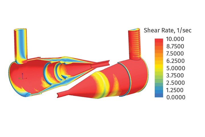
FIG 1 Shear-rate contours in a side-fed tubing die.
Also, there appeared to be several “step changes” in the geometry, which result in stagnation zones where the polymer ultimately degrades. A more properly designed die would avoid these types of problematic conditions.
Spiral Crosshead Die Analysis
Pressure contours on the tubing die with a spiral-mandrel type distributor were also monitored. Pressure drop appeared excessive and about twice the pressure drop through the side-fed die. Velocity contours were plotted on a cross-section and, in relief, at the die exit. The latter appeared to be very uniform.
Figure 2 shows velocity contours, in relief, at the end of the spiral-mandrel distributor. The velocity contours at the end of the distributor appear to be very uniform, indicating that the spiral mandrel distributed the material successfully.
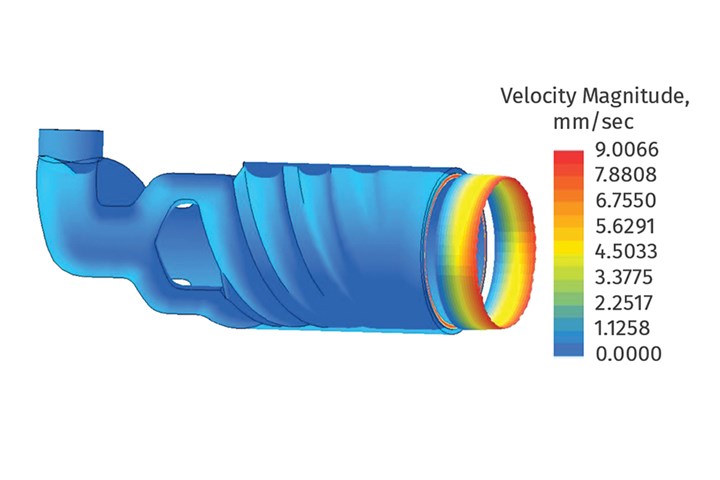
FIG 2 Velocity contours from the spiral-mandrel distributor.
Color contours of the shear rate were plotted with a maximum scale set at 10/sec. It appeared that the critically low shear rates on the wall (blue regions) were caused primarily by the step changes in the flow field.
Color contours of the shear stress on the step changes were very low too, resulting in stagnant regions where the polymer will most likely degrade.
There is a very low-stress region on the outer surface at the start of the conical transition as well. These low-shear-stress regions should be removed with an improved die geometry, since they will limit the duration of the run before the dies need to be cleaned. Also, and more importantly, very low-stress regions on the inner surface can result in polymer degradation that can break off and end up inside the product, where it may not be seen by quality control and potentially be delivered to the customer.
Figure 3 shows some path lines in the spiral-mandrel distributor. Path lines are often used to see how far around the circumference the flow from each spiral is distributed. The farther the material is spread around the circumference of the die, the better the uniformity in the final product.
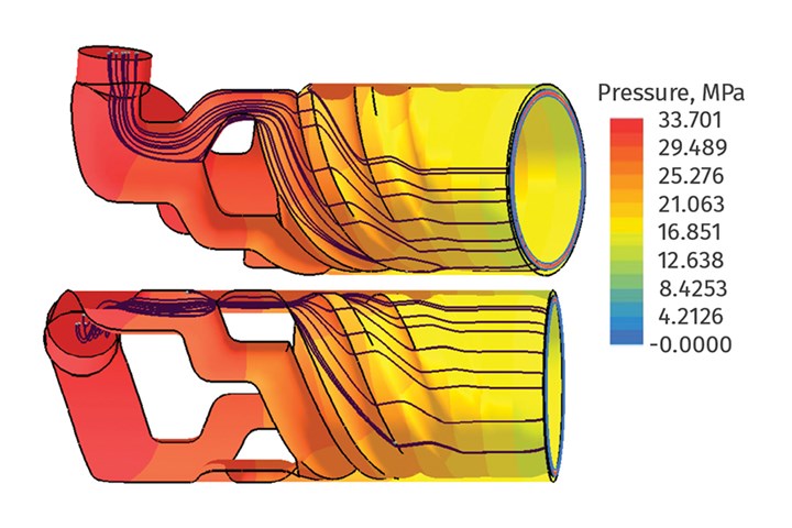
FIG 3 Path lines on pressure contours in the spiral-mandrel distributor.
Weld Lines
All dies that are designed to produce an annular product will, inevitably, create a weld line in the product. Table 1 shows the orientation of weld lines in three different types of annular dies.
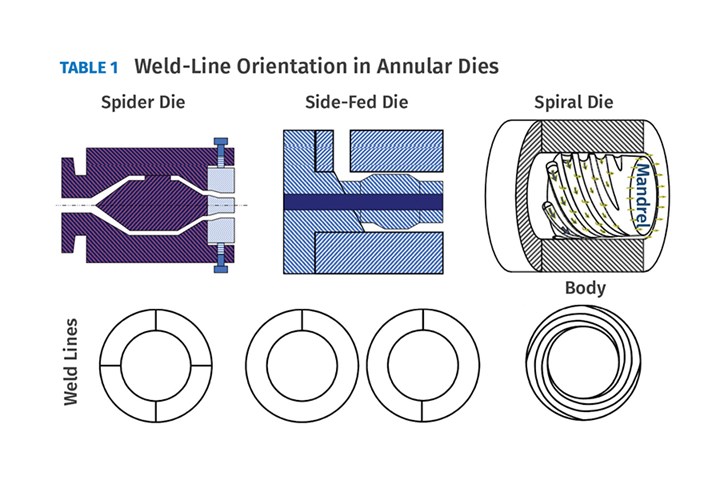
In most cases, a weld line is of no consequence; but, if it is formed with material that has a long residence time—and is possibly degraded—it may affect the strength of the final product in that region. The orientation of the weld line in the spiral-mandrel die results in an inherently stronger structure. Tubing produced with a spiral-mandrel type of distributor is also more resistant to “kinking.”
Multi-Lumen Die Optimization
Multi-lumen tubing has two or more channels used to convey different materials during a medical operation. The overall diameter of the tubing is very small, often less than 5 mm, and may contain three or four separate channels. A multi-lumen tube with four channels and an overall diameter of 2.5 mm is considered here.
The dimensional details of the geometry are redacted due to client confidentiality. The processor reported that the tubing required a long trial-and-error development process to make an acceptable product. Also, every startup required “significant tweaking to get the product back in spec.” Moreover, it was reported that the process was very unstable, and the product dimensions were frequently out of tolerances.
Flow balancing consisted of adjusting the geometry at the die exit to try to achieve the required product shape. Furthermore, there were many abrupt changes to the geometry, which are not desirable for stable operations.
Figure 4 shows color contours of the velocity from a flow simulation of the original die-exit geometry, using half-symmetry for the analysis. The calculated percentage flow (shown in light or dark blue) in various regions of the cross-section and the required percentage flow (in black between parentheses) are based on the required final product shape. The numbers in light blue indicate that the flow is higher than required, while the numbers in dark blue indicate less than the required flows.
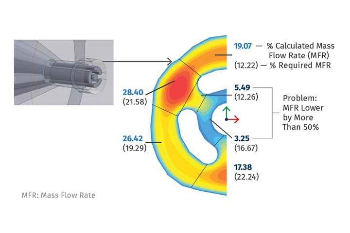
FIG 4 Simulated MFR distribution at die exit (half-symmetry) in a multi-lumen tubing.
Color contours of the pressure field in the die tip were plotted. The maximum pressure drop through the area was predicted to be about 38 MPa (5500 psi), which is quite high for such a relatively short region.
Color contours of the velocity in this area were monitored—in particular, the maximum velocity in three regions of the flow field. The maximum velocity was found to be 7.9 mm/sec at entry to this region, before increasing to 185 mm/sec at the region with the smallest diameter, then abruptly decreasing to 78 mm/sec just prior to the die exit. These large and rather abrupt changes in the velocity suggest that the polymer melt is experiencing large changes in elongational (or extensional) deformation.
Path lines in the flow field were monitored, and graphs of the elongation rate along such path lines were plotted. Graphs showed that the material flowing from the conical region to the smallest-diameter region experienced an abrupt increase in elongational deformation to about 200/sec then dropped to about -350/sec as it entered the region just prior to the die exit. A negative elongation is essentially a compression.
These abrupt changes in elongational deformation bring into play the polymer’s elongational viscosity, which is a resistance to acceleration or deceleration. This is another material characteristic of polymers. Elongational viscosity could be measured and incorporated in the design of a die, but this property cannot be controlled very well during resin production and can vary significantly from lot to lot. Table 2 summarizes the results of the analysis on the original die.
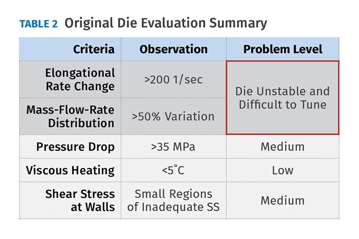
The evaluation summary indicates that the major problems with this die are the large elongational deformations and the poor polymer distribution. The pressure drop is higher than necessary, but that does not really cause problems other than the extruder having to work a little harder to deliver the material. The analysis also reviewed viscous heating, which was relatively small, and wall shear stress, which showed small regions of very low shear stress and potential degradation. As such, it was recommended that the die-tip design be modified to correct these problems.
Correcting the Flow Balancing
There are potentially an infinite number of ways to balance the flow in a die, but they all involve adjusting the relative resistance to achieve the required flow distribution. Still, some methods tend to be more practical than others.
Velocity contours in the original die-exit shape were plotted along with flow-balancing options:
• Option 1 was to modify the outside diameter of the geometry to alter the resistance in different regions, but this may affect the roundness of the final product.
• Option 2 was to modify the pins that are inserted to create the multi-lumens, but this may affect the lumen shape. Also, these pins are quite small and could easily be deflected by the flow.
• Option 3 was to add smaller pins in the high-velocity regions to create more resistance and reduce the flow in these regions. However, it was determined that such pins would also be too small and impractical.
Simulation determined that the most practical solution would be to make a die with essentially three new sections. The new design would include a “balanced plate,” which is the section in which the flow distribution would be balanced very precisely to what is required for the final product. Also, the length of this section would be designed to have the largest resistance within the die. This would ensure that this section would have the most control over the flow distribution.
Next, there will be a short, tapered, transition plate, which leads to the die exit plate. The exit plate will essentially have the same shape as the final product but scaled up about five times to account for the drawdown.
Close-ups of the balanced plate and the three flow restrictors cut into the outer plate were viewed through simulation. The flow restrictors were oriented in the open region that had too much flow, and were optimized in size to obtain a flow distribution within 5% of the target distribution, as shown in Fig. 5.
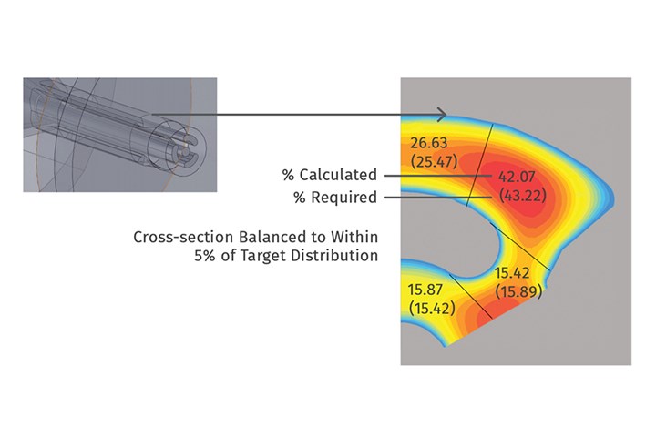
FIG 5 Balancing plate cross-section flow balance (1/3 symmetry).
The new design was expected to have a pressure drop of about 32 MPa, which is about 6 MPa less than the original design.
Elongation Rate
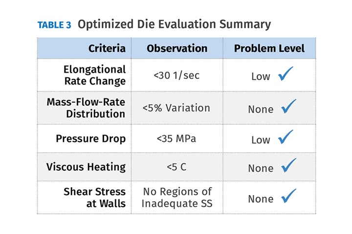
Elongation rates were graphed along path lines in the new design. It was evident from the scale of the graphs that the elongational deformations were significantly reduced in the new design. Table 3 summarizes the criteria in the new design.
Performance of Optimized Design
The proposed new design was delivered and plates manufactured accordingly. It was reported that after an initial trial, a small modification was required to achieve the desired product specifications. After this, it was also reported that startups were much faster, with very little startup scrap, and then very stable production with negligible sensitivity to material lot-to-lot variation. The Cpk on key dimensions was >2.0.
Extrusion simulations based on the VEL software proved here to be useful in anticipating issues and running “what-if” scenarios to size extruders and design associated dies for plastics extrusion projects. Simulations should be used at early stages of any project to avoid trial and error and the remaking of tooling.
ABOUT THE AUTHOR: Dr. Ben Chouchaoui is a technical consultant for Windsor Industrial Development Laboratory Inc., Windsor, Ont., where he has worked since 2009. In his career, he has boosted technical capabilities of employers in FEA/CAE and CFD/CAM; established laboratory and simulation tools for demanding functional systems; correlated numerical calculations to processing and durability tests of products; supervised engineers; managed government-funded research; developed and maintained client accounts; and trained new engineers and R&D personnel in FEA and CFD. Contact: 519-991-8919; bencho@windsorlabs.ca.


Related Content

High-Output Extruder Series Now Comes in Smaller Size
Series offers higher output, lower melt temperatures and energy savings.
Read More
New Rotary Die and Cam Lock Design for Tubing
NPE2024: New design enables quick and easy assembly and disassembly of the crosshead, and eliminates the socket head cap screws.
Read More
Big-Pipe Processor Saves Big on Materials
Egyptian pipe producer saves more than $1 million in materials to produce large-diameter pipe thanks to battenfeld-cincinnati extrusion technology.
Read More
Novel Profile Cooling Technology Promises Big Output Boost
Aimed at complex profiles such as PVC lineals, retrofittable system adds turbulent cooling to calibrator to boost output by 25-50%.
Read MoreRead Next

Four Keys to Consistent Tubing
Because of their use in critical applications, processors of medical tubing have little or no room for error.
Read More
Medical Tubing: Use Simulation to Troubleshoot, Optimize Processing & Dies
Extrusion simulations can be useful in anticipating issues and running “what-if” scenarios to size extruders and design dies for extrusion projects. It should be used at early stages of any project to avoid trial and error and remaking tooling.
Read More
The Role of Screw Design In Efficient Extrusion Of Medical Devices
For extruders of medical tubing, screw design plays a key role in maintaining dimensional control, physical properties, and more.
Read More