
How to Achieve Simulation Success in Molding, Part 3: Inputs, Reports and the Analyst
Ultimately the success of this virtual, digital software falls to the real-world, analog humans requesting and completing the analysis.


In this three-part series of articles, we have outlined the components of a successful molding simulation, including the questions to ask and key factors to consider that will ensure it is completed correctly from the start. In parts one and two, we discussed models, meshing and material characterization. In part three, we will wrap up with the remaining factors: processing inputs, detailed reports and the analyst.
Process Inputs
Process inputs for simulation can often be tricky, as the analyst does not always have the same settings or feedback that a process engineer might. The biggest question when reviewing simulation results would be: How are those process settings determined? Is the analyst using the simulation program’s default settings, or have they been optimized for your application? Default settings can be a starting point, but the analyst should continue to adjust and optimize, and therefore those defaults should not end up in the final report.


More often than not, the machine barrel details are not modeled into a simulation. You will see machine and screw conveyance losses on the molding floor that were likely not accounted for in the simulation.
Figure 1 shows an example of process settings from a substandard report. First of all, this is an awkward way to share the processing information, as it is an image from the simulation log file and difficult to read. A few lines are highlighted in this example. The fill time is one second and has been determined by the automatic calculation. Again, this may be a fine starting point for early analyses but should not be used when runners are present.
In this analysis, runners were modeled, thereby making the automatic setting a poor choice resulting in inaccurate fill speeds. Cooling time was also set to automatic. This will ensure that not only will the part and runners be completely solidified but also that the average cavity surface temperature will be within one degree of the target mold temperature. Unfortunately, this often results in long, unrealistic cycle times, which then affect the warpage calculations as you are essentially using the tool as a cooling fixture.
The packing profile used the default settings of 80% of the fill pressure for 10 sec. Is that pack pressure too high or too low? Is the pack time long enough so the gate will seal while still under packing pressure? The packing profile would obviously impact the warpage calculations, but also the clamp-tonnage predictions.
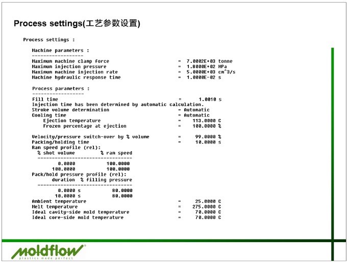
FIG 1 In this analysis, the process settings were left as default values. Photos: American Injection Molding Institute
One last item to review in the process settings shown in Fig. 1 would be the temperatures. Often, analysts use the default mid-range temperatures, as shown above, but problems may arise when the temperatures deviate from reasonable molding conditions. In Fig. 2, the left image shows the analyst’s view of Moldflow’s recommended processing. The first and second lines are the default melt and mold temperature, and are typically the midpoint of the min-max melt and mold ranges.
In this example, the midpoint of 255°C and 295°C provided the default value of 275°C. Unfortunately, that is actually the maximum recommended melt temperature from the material’s datasheet. Unless the process engineer also used the high end of the melt temperature range, we should expect greater discrepancies when trying to correlate to real-world results.

FIG 2 At left, the datasheet ranges for a PC/ABS, and at right, the melt and mold temperature ranges supplied by the simulation software.
Obviously, any differences in processing conditions will impact the end results. Other setup and workflow information should also be reviewed. Was the simulation for just the cavity and not accounting for the flow and/or pressure through the feed system? More often than not, the machine barrel details are not modeled into a simulation. You will see machine and screw conveyance losses on the molding floor that were likely not accounted for in the simulation.
Was the cooling modeled, or was an isothermal condition used for warpage predictions? Depending on the cooling design, both warpage magnitude and trending have the potential to change. If the simulation did have cooling modeled, are the lines plumbed the same as on the molding floor? Is the cooling pressure or flow rate limited on the floor versus fully turbulent in the simulation? The more information provided upfront, the greater the chances for success.
Sharing the Results
The ability to communicate the results is a crucial step in the simulation process. Nowadays, there are many ways an analyst might choose to do this: PowerPoint or PDF reports, video conferencing or Moldflow Communicator files, to name a few. A combination of these methods might be ideal.
Analysts are documenting and communicating the results, and should be able to thoroughly explain the results and offer potential solutions.
Moldflow Communicator is a free viewer that enables anyone with a Communicator (.mfr) file to review the simulation results in a more interactive way. The viewer enables the end user to rotate the part, zoom in, play the animations, take measurements and more, providing the ability to really dig into the results.
Whether it be in Word, PPT or a PDF, an actual written copy of the report can also be helpful. It not only provides a better opportunity to document any issues or concerns but the ability to print it may make it easier to share with others.
Written reports should be more than just “pretty pictures,” and also include supporting outputs and detailed explanations. Use caution when reviewing reports that show the same orientation throughout the report. The lack of cross sections, close-up views and poor scaling are also of concern. These missing details typically indicate that not a lot of time or effort was put into the report.
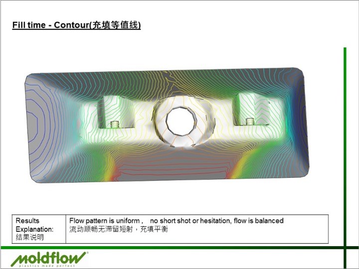
FIG 3 Use caution with canned statements on reports. The flow pattern is neither balanced nor uniform, and there is a considerable amount of hesitation shown.
Qualified Analysts
You may have noticed that the analysts are the ones making the bulk of the decisions we have been discussing through these articles. They are deciding both the mesh type and density, and picking the processing settings. While they likely do not have any control over the level of the material characterization, they do have the ability to highlight the characterization level and its impact to the end user. They are also the ones documenting and communicating the results, and should be able to thoroughly explain the results and offer potential solutions, if needed.
If you are the one contracting the simulation, you are not without responsibility. It is important to have upfront communication and to clearly define both the scope and limitations.
Understandably, the experience level of the analyst can also play a significant role. They need to have knowledge of the key inputs and meshing requirements, but also a full understanding of both the capabilities and the limitations of the software. The analyst needs to know how to interpret and apply the results, ideally coupled with practical injection molding experience. Having a good foundation of plastics rheology, along with part and mold design knowledge, will aid in both upfront engineering and troubleshooting.
Certification in the software may demonstrate experience, and some companies even require analysts to obtain their Expert Certification in order to work on their projects.
Communication Is Key
If you are the one contracting the simulation, you are not without responsibility. It is important to have upfront communication and to clearly define both the scope and limitations. Successful simulation projects should have kickoff meetings to discuss what you are looking to learn from this analysis and any limitations you may have.
Examples here could include: allowable gating surfaces and maximum injection pressures and/or clamp tonnages. Is there any other information you can provide? Are there any known issues with this part or similar parts? Do you have an idea, based on similar applications, of initial processing conditions? It is also important to provide up-to-date models to the analyst and keep them aware of any design changes as the project progresses.
Downstream follow-up is also important. Commit to using the data from simulation and sharing it with the appropriate personnel. It is sometimes surprising to speak with process engineers who know a Moldflow analysis was completed, but the report was never shared with them. These reports contain pertinent information that may aid in process development by giving reasonable ranges and potential starting points.
It is sometimes surprising to speak with process engineers who know a Moldflow analysis was completed, but the report was never shared with them.
To get the most out of your simulations, consider creating a Moldflow standard for your company. This might include detailed setup instructions and best practices, as well as specific result plots required in the report. Couple this with correlating the analysis results against actual molding. You may find it useful to compare short-shot progressions, pressure readings, warpage measurements and more. By recording and tracking these comparisons, you gain knowledge and confidence in the data, making you smarter for your next project.
Bringing It All Together
Throughout this three-part series of articles, we have been reviewing the key factors for a successful simulation: accurate models, quality meshes, thorough material characterization, realistic process settings, a qualified analyst, and the time to do the job right. All of these aspects are necessary for a successful simulation.
Simulation shows us one perfect snapshot in time. While it cannot account for inherent variation in the mold and molding process, when used upfront with proper inputs and expectations, it can be an invaluable tool helping us make better informed decisions.
ABOUT THE AUTHOR Jennifer Schmidt is the senior Moldflow instructor at the American Injection Molding (AIM) Institute. She has more than 20 years’ experience in the plastics industry, with a focus on flow simulation. She is a Certified Moldflow Expert and GM-Approved Moldflow Analyst. Schmidt earned a bachelor’s degree in plastics engineering technology from Penn State Erie. Contact: 866-344-9694; jschmidt@aim.institute; aim.institute.com


Related Content

How to Select the Right Tool Steel for Mold Cavities
With cavity steel or alloy selection there are many variables that can dictate the best option.
Read More
How to Optimize Pack & Hold Times for Hot-Runner & Valve-Gated Molds
Applying a scientific method to what is typically a trial-and-error process. Part 2 of 2.
Read More
How to Stop Flash
Flashing of a part can occur for several reasons—from variations in the process or material to tooling trouble.
Read MoreRead Next

How to Achieve Simulation Success, Part 2: Material Characterization
Depending on whether or not your chosen material is in the simulation database — and sometimes even if it is — analysts will have some important choices to make and factors to be aware of. Learn them here.
Read More
How to Achieve Simulation Success, Part 1: Model Accuracy and Mesh Decisions
Molding simulation software is a powerful tool, but what you get out of it depends very much on your initial inputs. Follow these tips to create the most successful simulation possible.
Read More