
How to Optimize Pack & Hold Times for Hot-Runner & Valve-Gated Molds
Applying a scientific method to what is typically a trial-and-error process. Part 2 of 2.


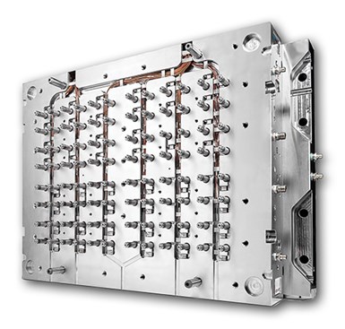
In valve-gated hot-runner molds, there is no need to differentiate between pack and hold times, because once the gate is mechanically shut after packing, the holding phase does not exist. Photo Credit: Milacron
In a previous article, we discussed the theory and procedure of optimizing the pack and hold times for hot-runner and valve-gated molds. Although the pack and the hold phases technically should be differentiated, for the sake of introduction to the topic they both were considered as one phase: the holding phase. This article will delve into the theory of differentiating between the pack and hold phases, followed by the procedure to optimize these phases.
To recap, there are three phases during the filling of the mold:


1. Injection phase: In theory, during this phase the cavity is fully filled with molten plastic. But since plastic melt is compressible, in practice no one really knows if the mold is 100% filled with melt or is filled more than 100%. For this reason, the mold is typically filled to about 95-98% in the injection phase.
2. Pack phase: During this phase additional plastic is injected into the cavity to compensate for the shrinkage that occurs in the plastic that was injected in the injection phase. This is a pressure- and velocity-controlled phase.
3. Hold phase: Once the required amount of plastic is injected into the cavity, it must be held there until the gate freezes off. This is a time-controlled phase during which no more plastic is injected.
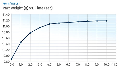
In most cases, molders do not differentiate between the pack and hold phases and will typically have only one pressure setting and one time setting for both phases. They call this the hold phase. The optimization of this phase is done by the gate-seal study, where the part weight is plotted against time. Once the gate freezes off, the part weight stays constant. The molder adds a second or so to the time where the part weight stabilizes and sets this as the gate-seal time. However, in some cases this does not work well. In such cases, a part weight vs. time study will never show a flat region such as the one shown in Fig. 1.
Here are some typical scenarios where pack and hold must be differentiated:
• With softer materials such as polyolefins, TPEs, and TPUs, the part weight continuously increases and does not stabilize in the gate-seal test.
• In sprue-gated parts, the gate size is big, and waiting for this to freeze off could be impractical. Part weight will also increase with time and will lead to stress buildup in the gate area.
• In some parts there is stress failure at the gate—such as in trash cans where the part is center gated, and the most likely failure is a crack or break through the gate
• In hot-runner molds, since the gate is always molten, it will never seal as long as there is movement of plastic.
• In valve-gated molds there would be only pack and no hold since the gate is mechanically closed
• Sometimes cosmetic defects such as a gate vestige can be eliminated by adding two stages. (Gate vestige is a mold issue and must be fixed in the long run.)
In all these scenarios, the required amount of plastic must be injected in the pack phase, and this plastic must be retained during the hold phase until the gate freezes off. If the hold phase is terminated before the gate is frozen, the pressurized plastic in the cavity will flow back out of the cavity, often causing sinks and/or dimensional variations and issues. (This is the reason that a molder will notice sink on parts with high pack and hold pressures. When the molder lowers the pressure the sink disappears, often baffling the molder, since it is the opposite of what’s expected.)
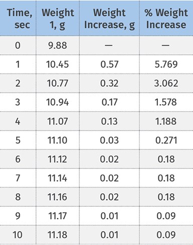
Here, the part-weight increase at 5 sec is about 0.03 g and tapers down more with time. The 0.03 g is about 0.25% of the final part weight (11.23 g) and 0.02 g is about 0.17% of the final part weight. So the part has reached very close to the required part weight—in other words, the pack phase has been completed at 5 sec.
First, consider a cold-runner mold and learn how to optimize these phases. Let’s illustrate this with an example. Consider the graph shown (right). It can be observed that the part-weight increase at 5 sec is about 0.03 g and tapers down even more as the time increases. The 0.03 g is about 0.25% of the final part weight (11.23 g) and 0.02 g is about 0.17% of the final part weight. So the part has reached very close to the required part weight; in other words, the pack phase has been completed at 5 sec in this example.
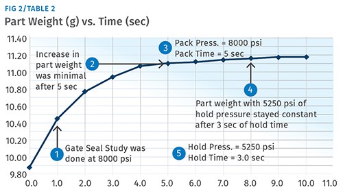
This is akin to packing luggage. Initially, clothes can be packed until the travel bag seems physically full, and more clothing can be put inside only after compressing the clothes that were first put in. As the bag is filled more and more, lesser and lesser additional amounts of clothes can be packed in there. So after the initial quick fill, further additions slow down. The pressure used during this initial phase is the pack pressure and the time that this pressure is applied is the pack time (see Fig. 2). In this example, the pack pressure is 8000 psi plastic pressure and the pack time is 5 sec.
Going back to the travel bag example, once we have packed the required amount of clothes, we must now zip it up in order to hold the clothes in there.
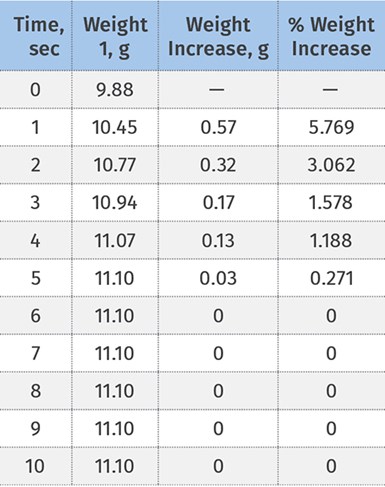
Results of a study to determine how to optimize pressures and times for pack and hold phases. Note that the increase in the part weight was minimal after 5 sec (2).
If not, the bag top or cover will not be able to keep the clothes contained. Similarly, once the required amount of plastic is now present inside the cavity it must be held in there. This is done by applying another pressure setting that will be lower than the pack pressure, until the part weight stabilizes—that is, until the gate freezes off. The target part weight here will be the same part weight that was obtained at the end of the pack time. In the experiment above, this hold pressure was 5250 plastic psi and the hold time was determined to be 3 sec. The total of pack and hold time was 5 + 3 = 8 sec. The final part weight was 11.10 g.
Determining Pack & Hold Pressures, Times
Optimization of this phase is Step Five in the Six-Step Study for Process Optimization. It is assumed that the previous four steps have been completed. (Please refer to fimmtech.com for info on the Six-Step Study.) Step Four is the Cosmetic Process Window Study that determines the high and the low for the second-phase pressure.
For this procedure, we’ll refer to the same info in the graph in Fig. 2, starting from the steps to generate the graph:
1. Set only one pressure collectively for pack and hold. Let’s call this the compensation pressure. Therefore, Compensation Pressure = Pack Pressure + Hold Pressure. Let us consider this pressure to be 8000 psi plastic pressure.
2. Set only one time collectively for pack and hold. We will call this the compensation time. Therefore, Compensation Time = Pack Time + Hold Time. Let us consider this time to be 15 sec.
3. Start with the compensation time at zero sec and generate a graph of Part Weight vs. Compensation Time up to 15 sec (Fig. 1).
4. Observe the graph and the part-weight table to estimate where the change in part weight begins to slow down. A change in the slope of the graph can be seen. In Fig. 1 this time can be considered as 5 sec. Based on this, Pack Pressure = 8000 psi and Pack Time = 5 sec. Record the part weight; this will be the Pack Only Part Weight = 11.10 g.
5. Initially we had only set one value for pressure and time and called it compensation pressure and time. We split the compensation pressure and time into two and identify them as pack pressure, pack time, hold pressure, and hold time.
Therefore, on the molding machine we will now add another pressure and time profile. The first will be the pack and the second will be the hold. Set the first pressure to 8000 psi and the first time to 5 sec.
6. The second set of pressures are the hold pressures and hold time. Since the compensation time was set to 15 sec, and the pack time was set to 5 sec, set the hold time to 10 sec (15 – 5=10).
7. Set the hold pressures equal to the value of pack pressures (8000 psi) and mold parts.
8. Record the part weight. This should be the same as the 15-sec value above and should therefore be equal to 11.23 g. It will be higher than the Pack Only Part Weight of 11.10 g.
9. Drop the hold pressure in steps of about 250 plastic psi and keep checking the part weight at every reduction. The pressure at which the part weight equals the pack-only part weight of 11.10 g will be the holding pressure. In this example, the value was 5250 psi.
10. Next reduce the hold time in steps of 1 sec and note the time where the part weight drops below 11.10 g. In this example, this time setting was 2 sec since at 2 sec of hold time the part weight was 11.08 g. This means that at 2 sec the plastic is coming back out from the cavity. Add a second to 2 sec, making this time 3 sec, which will bring the part weight back up to 11.10 g. This will be the set holding time.
The results are summarized in Fig. 2. Final Settings:
• Pack Pressure =8000 psi
• Pack Time=5 sec
• Hold Pressure =5250 psi
• Hold Time=3 sec
Hot-Runner & Valve Gated Molds
In the previous article, we described a procedure for optimizing pack-and-hold times for hot-runner and valve-gated systems. The procedure will work very well for the majority of molds in which just one compensation phase is sufficient. But what if there is a part that needs to be packed out to get rid of sink, but doing so results in stress buildup at the gate? In such cases, the procedure described above can be used for hot-runner molds without any modification. This would be an alternate procedure to the Visual Inspection Template method. One will still need to perform the DOE for dimensions.
In the case of hot-runner molds, the weight increase with the time increment is usually steeper than with a cold-runner mold, and therefore some past molding experience is helpful when determining the change in the slope in the graph. When it comes to valve-gated parts, since the valve is mechanically closing the gate, once the pack time is determined with the above procedure the valve must be shut. In valve-gated molds, the holding phase will not exist.
Optimizing for Dimensions
The procedure above says nothing about dimensions. To find the optimum settings for obtaining the required dimensions requires a DOE using pack pressures. The pack pressure of 8000 plastic psi was used, based on the highs and the lows of the Cosmetic Process Window from Step No. 4 of the Six-Step Study. Considering that the low and the high were 6000 and 10,000 plastic psi, these would also now be the values to be used in the DOE. The pack time, the hold pressure, and the hold time should be kept constant. There is a possibility that the hold pressure could change if the hold time is not optimized correctly. It is therefore important that the hold time is always sufficient, with a second or so of buffer.
Some molders cut short pack and hold times to get a faster cycle. But remember that to get a desired quality, the part will need to cool for a finite amount of time. The actual time the part has cooled is equal to Injection Time + Pack Time + Hold Time + Set Cooling Time. Reducing any one of these will require the processor to increase another one of these so that the overall actual cooling time remains unchanged.
Depending on part geometry and part thicknesses, the packing phase may have to be further profiled. This is perfectly acceptable. The theory and the procedure described above are excellent starting points to optimize the pack and hold phases.
ABOUT THE AUTHOR
Suhas Kulkarni is the founder and president of Fimmtech, San Diego, an injection molding service-oriented firm focusing on Scientific Molding. Fimmtech has developed several custom tools that help molders develop robust processes, and its seminars have trained hundreds of individuals. Kulkarni is an author of the best-selling book, Robust Process Development and Scientific Molding, published by Hanser Publications. Contact: (760) 525–9053; suhas@fimmtech.com; fimmtech.com


Related Content

Why Shoulder Bolts Are Too Important to Ignore (Part 2)
Follow these tips and tricks for a better design.
Read More
How to Mount an Injection Mold
Five industry pros with more than 200 years of combined molding experience provide step-by-step best practices on mounting a mold in a horizontal injection molding machine.
Read More
Back to Basics on Mold Venting (Part 1)
Here’s what you need to know to improve the quality of your parts and to protect your molds.
Read More
Cooling Geometry and the Reynolds Calculation
The original Turbulent Flow Rate Calculator worked well with a round circuit diameter, such as a drilled passage, but not as well using hydraulic diameters. Here’s how the problem was fixed.
Read MoreRead Next

Optimizing Pack & Hold Times for Hot-Runner & Valve-Gated Molds
Using scientific procedures will help you put an end to all that time-consuming trial and error. Part 1 of 2.
Read More
People 4.0 – How to Get Buy-In from Your Staff for Industry 4.0 Systems
Implementing a production monitoring system as the foundation of a ‘smart factory’ is about integrating people with new technology as much as it is about integrating machines and computers. Here are tips from a company that has gone through the process.
Read More
Processor Turns to AI to Help Keep Machines Humming
At captive processor McConkey, a new generation of artificial intelligence models, highlighted by ChatGPT, is helping it wade through the shortage of skilled labor and keep its production lines churning out good parts.
Read More