


Injection molding simulation is becoming more mainstream for new product development, as it can be a great tool to predict and correct issues up front while product and tooling designs are being finalized. Acting on this information requires confidence in the results, but how do you know they are trustworthy? In this three-part series, we will answer the question, “What does it take to have a successful simulation project?” We will identify the key factors to consider and address how to ensure the process is run correctly from start to finish.
Model Accuracy
Let’s start where an analysis starts: with the models. Before diving in, there are some key questions to answer: Is the model given to the analyst the most up-to-date revision? Is the model provided only for the part cavity, or does it also include runner geometry and cooling design? Will the cores and cavities be manufactured using the same mold material, and what metal is specified? The more detail that can be modeled and simulated, the more accurate the results will be.


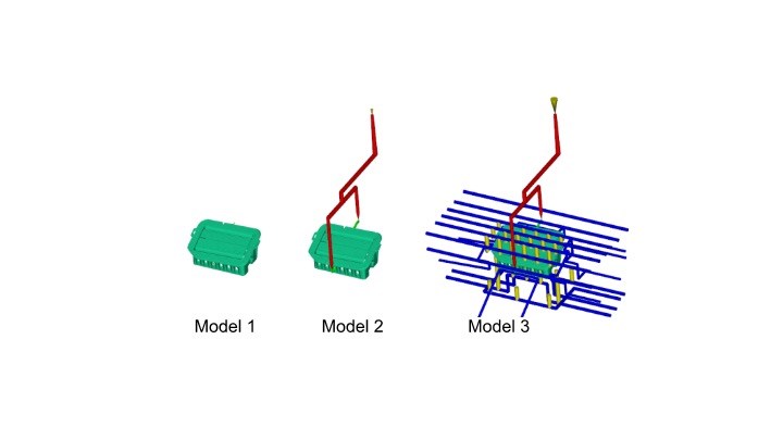
FIG 1 Three models of the same part: Which one would provide the most accurate results?
(Images: American Injection Molding (AIM) Institute)
As for the part model, it is important to determine whether the model provided is the finished part size, or if it has been expanded to account for the shrink rate of the material and, thus, the cavity geometry machined into the mold. This is especially important when reviewing warpage analysis results because the deflection results account for both shrinkage and warpage of the material. Therefore, if you intend to measure against the predicted magnitudes accurately, within a specified tolerance, the simulation needs to start with the expanded part data since the final deflection results will be factoring in shrinkage. Even the file type matters. Native CAD or STEP files tend to be the best choice, while STL files are the least desirable as they do not give the analyst as much flexibility with meshing.
Another factor to consider: mold-steel dimensions. Is the actual mold steel machined identical to what is modeled in the simulation? If we recall the Hagen-Poiseuille equation for pressure drop shown below:
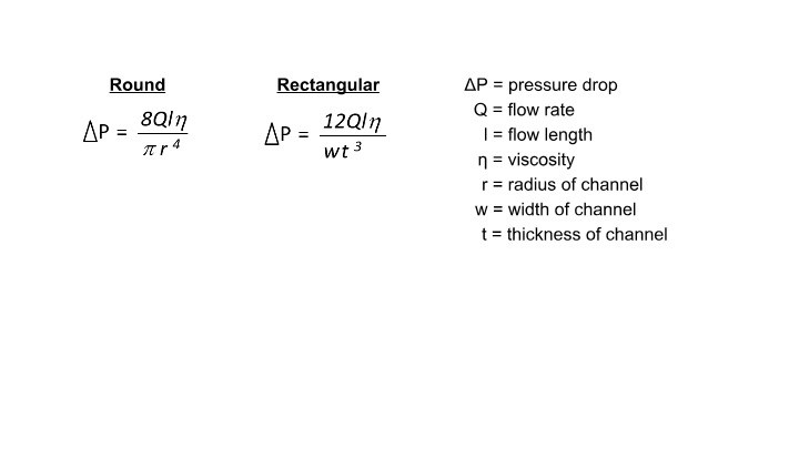
FIG 2 Hagen-Poiseuille Equation for pressure drop.
Small variations — even within a tolerance in dimensions such as runner or gate diameters and wall stock — can make a large difference in the actual pressure losses due to the exponents applied to the flow geometry variables. Consequently, the thicknesses must be represented correctly in the simulation. Additional issues with the mold such as runner mismatch, core/plate deflection and mold wear can also cause variations between the actual mold and the simulation model, typically beyond the analyst’s purview.
There are some best practices that deserve consideration when it comes to models within simulation. You might be able to remove small details, such as date stamps or resin identification lettering. Another is that the part should be rotated into “tool position,” meaning the parting plane of the part should be parallel to the XY plane in simulation, with the sprue typically positioned in the positive Z. This orientation won’t affect filling progressions or pressure predictions, but it is critical for clamp-tonnage predictions. The clamp-tonnage prediction is based on the projected area on the XY plane and the pressures seen throughout the cycle. So, if the part isn’t in the correct orientation, you risk miscalculating the clamp tonnage. Duplicated surfaces will duplicate the projected area, skewing the results, and thus should be manually excluded from the clamp-force calculations by the analyst.
Why Meshing Matters
Meshing quality can be two-fold. The first question is to determine which mesh type to apply to the model. In Autodesk Moldflow, there are three choices: Midplane, Dual Domain and 3D. Many decisions go into selecting the correct type of mesh for a given part, with part geometry and wall thickness typically being the major drivers of this decision. If your part geometry is thick and chunky (officially defined as less than a 4:1 width-to-thickness ratio) — or has thick and chunky features — a 3D mesh should be used to properly capture the thicknesses. Other decision drivers can be material characterization, required analysis sequences and/or molding processes, the need to use inertia and gravity solvers, and specifically desired results —since not all result options are available for every mesh type.
Another important consideration regarding mesh-type selection is that different meshes use different solvers and assumptions. Midplane and Dual Domain use the same solvers for filling, fiber orientation and warpage calculations. They also have mostly the same background assumptions. 3D meshes generally make fewer assumptions, especially in regard to calculations done in the thickness direction and for heat transfer. They also use different solvers than Midplane and Dual Domain for filling, fiber orientation and warpage. This means for the same part applying meshed Dual Domain versus 3D, and analyzed with identical material and processing conditions, the software could predict different results. Often, this might just be differences in magnitudes, but in some cases, it might also result in differences in trending. Clearly, the mesh choice can affect the overall accuracy.
Mesh density is the other element of meshing and mesh quality to consider. Too coarse a mesh can cause errors in the filling progression, overlooking defects like air traps, weld lines, hesitation and racetracking. The tighter the mesh that is applied, the more accurate the results …. to a certain extent. Eventually there is a point of diminishing returns. Also, the tighter the mesh that is applied, the longer the computation time — and that is an exponential function. So, doubling the elements will likely more than double the computation time. It is often a balancing act for analysts to have a tight enough mesh to produce accurate results, but within a reasonable run time, all depending on the scope of the analysis.
Mesh density can be very visual, meaning it just “kind of” looks correct, and therefore is somewhat subjective. The main rule regarding mesh density is a minimum of three elements. An analyst will need to ensure that there is at least a minimum of three elements through features like thin-wall sections, living hinges, across gates, and where weld lines might form, to name a few. In addition to this rule, the mesh also needs to be fine enough to accurately capture critical details of the part.
The part shown in Fig. 3 has a nominal wall thickness of 0.060 in., with two side tabs of 0.015 in., or a quarter of the nominal wall thickness.
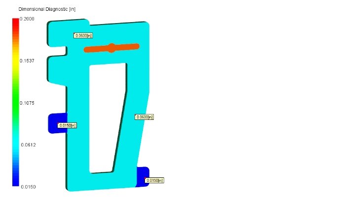
FIG 3 Part with thin tab features.
Figure 4 shows two mesh densities and their corresponding results when analyzed using the same material and process conditions. The first (left) shows a rather coarse mesh but technically meets the minimum-of-three-elements rule through the thin tabs. The second mesh (right) is much more refined, far exceeding the minimum of three elements required through the tabs.
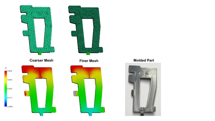
FIG 4 Comparing mesh density to molded parts.
There are obvious differences in the results. The first difference to note is that while the coarser mesh shows hesitation in one of the tabs, it does not show any short shots. The finer mesh shows both hesitation and short shots on both tabs (bottom left and bottom right). The second difference to note would be the development of the weld lines. The coarser mesh has more jagged weld lines, as they are displayed on the element edges. A more refined mesh provides for a higher resolution weld-line result. Another detail to note is that the coarse mesh shows the weld line going the full width of that top section, while the finer mesh results in a shorter weld line overall. The finer mesh will more accurately predict that the weld line transitions to a meld line as the flow front advances to the far end of the part. If we compare these results to the actual part molded to the same conditions, both tabs do indeed show incomplete fill, and the weld line isn’t visible over the full width of the part. The finer mesh certainly correlates more closely with the actual molded parts.
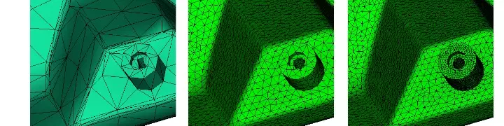
One final note on meshing: The foregoing examples were meshed at overall different densities, but on a global scale. It is possible for analysts to refine the mesh just in particular areas, either to better replicate complex part geometries or to further refine the results in specific areas. Some companies have Moldflow standards that require analysts to refine the mesh in areas of expected weld lines, to produce more accurate results. The example below shows three different mesh densities: the original mesh from the report of an outside tooling provider (unfortunately, a very poor mesh, likely by an untrained source); the default mesh out of the software; and a refined mesh from an experienced analyst. In this example, the boss feature was a source of breakage for the customer, and they wanted to use simulation to see if there were any potential improvements to be made.
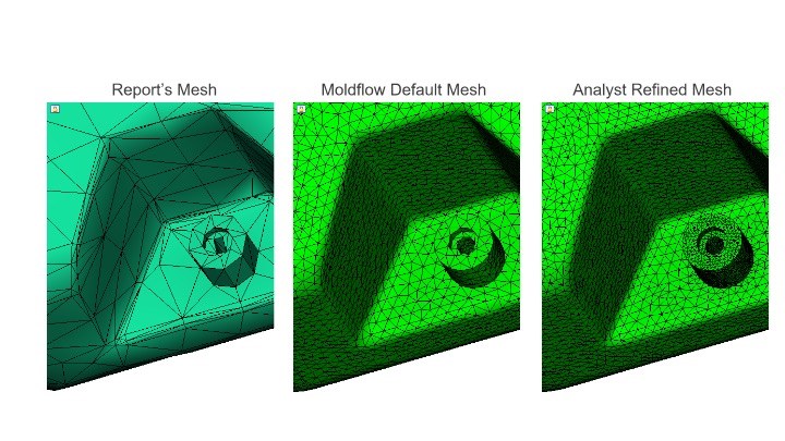
FIG 5 Refining meshes in specific part areas.
In the report mesh, the mesh is far too coarse and does not meet the minimum-of-three-elements requirement. As a result, the boss and the hole don’t reflect its cylindrical shape. The default mesh from the software has an improved mesh density and begins to better pick up the cylindrical features. However, with the refined mesh, the actual feature geometry is accurately represented, without increasing the element count globally. This is a simple step to give better quality results, especially since this feature was the focus.
Other Factors to Consider
Successful simulation projects will require accurate models and a high-quality mesh, but some other important aspects will also be addressed in upcoming articles in this series. These items include thorough material characterization, realistic process settings, use of a qualified analyst, and the time to do the job right. All of these aspects combine to make a successful simulation. There are no shortcuts! If any one of these areas is lacking, it will impact the accuracy of the entire project. In the next article in this series, we will continue this discussion with the influences of material characterization.
ABOUT THE AUTHOR Jennifer Schmidt is the senior Moldflow instructor at the American Injection Molding (AIM) Institute. She has more than 20 years’ experience in the plastics industry, with a focus on flow simulation. She is a Certified Moldflow Expert and GM-Approved Moldflow Analyst. Jennifer holds a Bachelor’s degree in Plastics Engineering Technology from Penn State Erie.


Related Content

How to Configure Your Twin-Screw Barrel Layout
In twin-screw compounding, most engineers recognize the benefits of being able to configure screw elements. Here’s what you need to know about sequencing barrel sections.
Read More
Use These 7 Parameters to Unravel the Melt Temperature Mystery
Despite its integral role in a stable process and consistent parts, true melt temperature in injection molding can be an enigma. Learning more about these seven parameters may help you solve the puzzle.
Read More
What to Look for in High-Speed Automation for Pipette Production
Automation is a must-have for molders of pipettes. Make sure your supplier provides assurances of throughput and output, manpower utilization, floor space consumption and payback period.
Read More
Injection Molding: Focus on these Seven Areas to Set a Preventive Maintenance Schedule
Performing fundamental maintenance inspections frequently assures press longevity and process stability. Here’s a checklist to help you stay on top of seven key systems.
Read MoreRead Next

Do Flow Simulation 'in the Cloud'
Autodesk Inc., San Rafael, Calif., has just made available a new version of its Moldflow Insight software that takes time-consuming meshing and analysis functions off your desktop and performs them at a remote data center accessed via the Internet.
Read More
Upgraded Simulation Package Adds Nozzle Zone & Conformal Cooling ‘Wizards’
Wizards assist conformal-cooling layout and simulation of melt compression in the nozzle in Moldex3D 2021.
Read More
Beaumont Tech Buys Material Characterization Business from Autodesk Moldflow
A trainer in mold analysis and supplier of simulation services acquires testing facilities used to obtain materials data needed for accurate simulation.
Read More