
Where and How to Vent Injection Molds: Part 3
Questioning several “rules of thumb” about venting injection molds.


This month’s column questions several “rules of thumb” about venting and is the third part in a three-part series. Part 1 in March addressed the basics of mold venting, while Part 2 in April dove into details of vent shape, dimensions, surface finish and more.
Venting the Cold Well
One rule of thumb says to vent the cold well opposite the sprue. Unless you’re concerned about the almost nonexistent possibility of getting a burn mark on the bottom of the cold well, which you might grind up and reprocess later, there is no need to add a vent there. The “slip fit” between the cold-well ejector pin and its bore is more than sufficient. What you may want to do is question the rules of thumb.


Venting the Runner
Another rule of thumb says you should add a vent to the runner in a two-plate or three-plate mold. That seems to make sense, because there is often a lot of air inside a runner system, and it helps to exhaust as much of it as possible so it doesn’t go into the cavity. Yet air, like plastic, takes the path of least resistance. Why would it want to squeeze through a vent 0.0005 to 0.0020 inch deep, when it can flow freely through a gate that is 10, 20, even 50 times deeper?
The answer is, it won’t—at least not until the air in the entire system (runner and cavity) starts to be compressed and build up pressure. When the pressure gets high enough, that’s when the vents in the runner become the paths of least resistance. Wherever the melt flow front is located when the pressure starts to build, any vent before that position is virtually useless.
Vents for flash traps can be much deeper.
Air volume is inversely proportional to the pressure applied to it. Just 150 psi of pressure will reduce the volume of air in a cavity by roughly a factor of 10. That’s why the most important thing to consider when trying to decide whether you need to vent a runner or not, is the ratio of the volume of air in the runner, divided by the total volume of air in the mold (runner plus all the cavities). Many molds have short runners feeding just one or two large parts. They have a small runner-air-volume ratio — usually less than 0.25. Venting any part of these runners is a waste of time.
Other molds have long runners, with several secondary runner branches feeding numerous parts, such as in an eight-, 16- or 32-cavity mold. This is where the runner-air-volume ratio can be high—about 0.75 or more. Venting these types of runners can be beneficial.
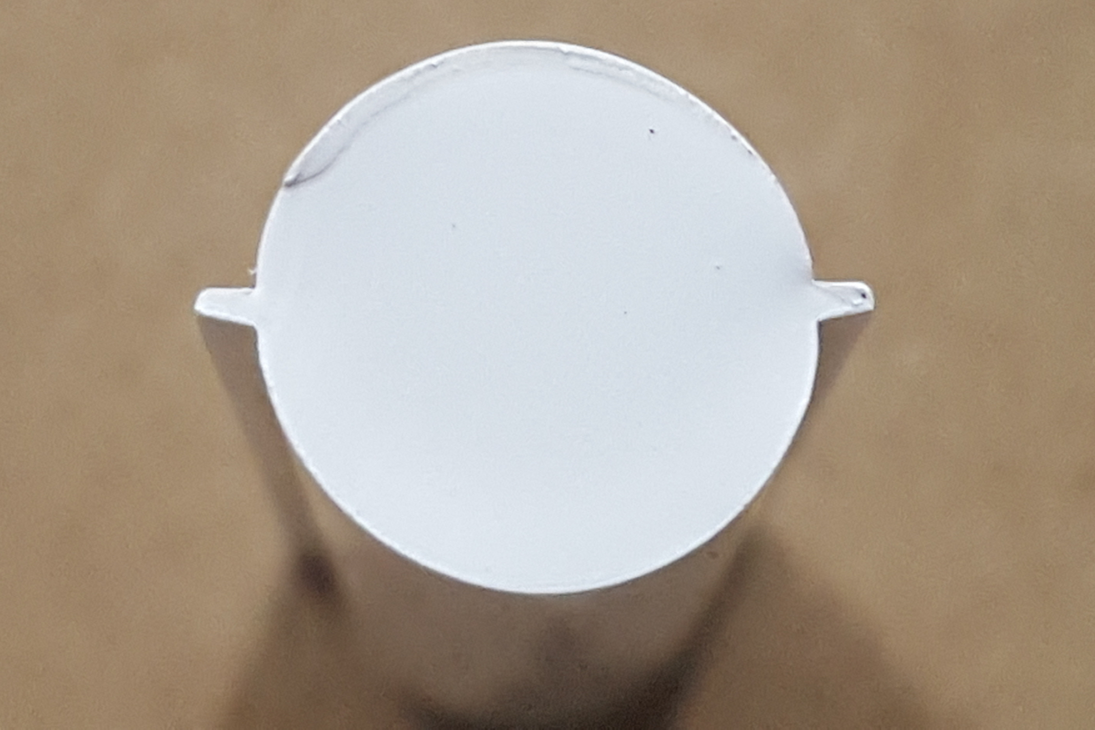
FIG 1 Cross-section of a full-round runner with flash traps. Images: J. Fattori
There is an effective trick for getting a significantly greater amount of air out of a runner system and that is to machine a flash trap, as shown in Fig. 1. Flash traps not only help prevent parting-line damage, they are also excellent at capturing air. The molten material will flow down the center of the runner channel first, leaving most of the flash trap empty of material.
When the pressure starts to rise due to either the air being compressed or the resistance of the plastic flow into the cavities, the material will start to push outward into the flash trap. If the flow front has not reached the end of the flash trap when the pressure starts to rise, the air inside the entire flash trap will compress — meaning more air volume that needs to be vented quickly. Vents for flash traps can be much deeper than material manufactures recommend— often double, sometimes triple their value. These deeper vents will now have a path of lower resistance then the other vents in the mold. Vented flash traps are just as effective in parabolic and trapezoidal runners as in full-round runners.
Whenever possible, try not to gate a part directly from the end of a runner. It is preferable to gate it from the side. We all know it is a good idea to have a runner overflow well at every runner turn, to capture any potential cold slug. The same logic applies to the end of the runner. You don’t want any potential cold slug to plug the gate or go directly into the cavity. You also want to vent the end of the runner to get as much air out as you can; but not too close to the gate, which reduces the amount of critical bearing surface. The gate is subject to some of the highest plastic pressures in the mold. You want to maximize the surface area around the gate to ensure a good seal and protect it from damage due to flash.
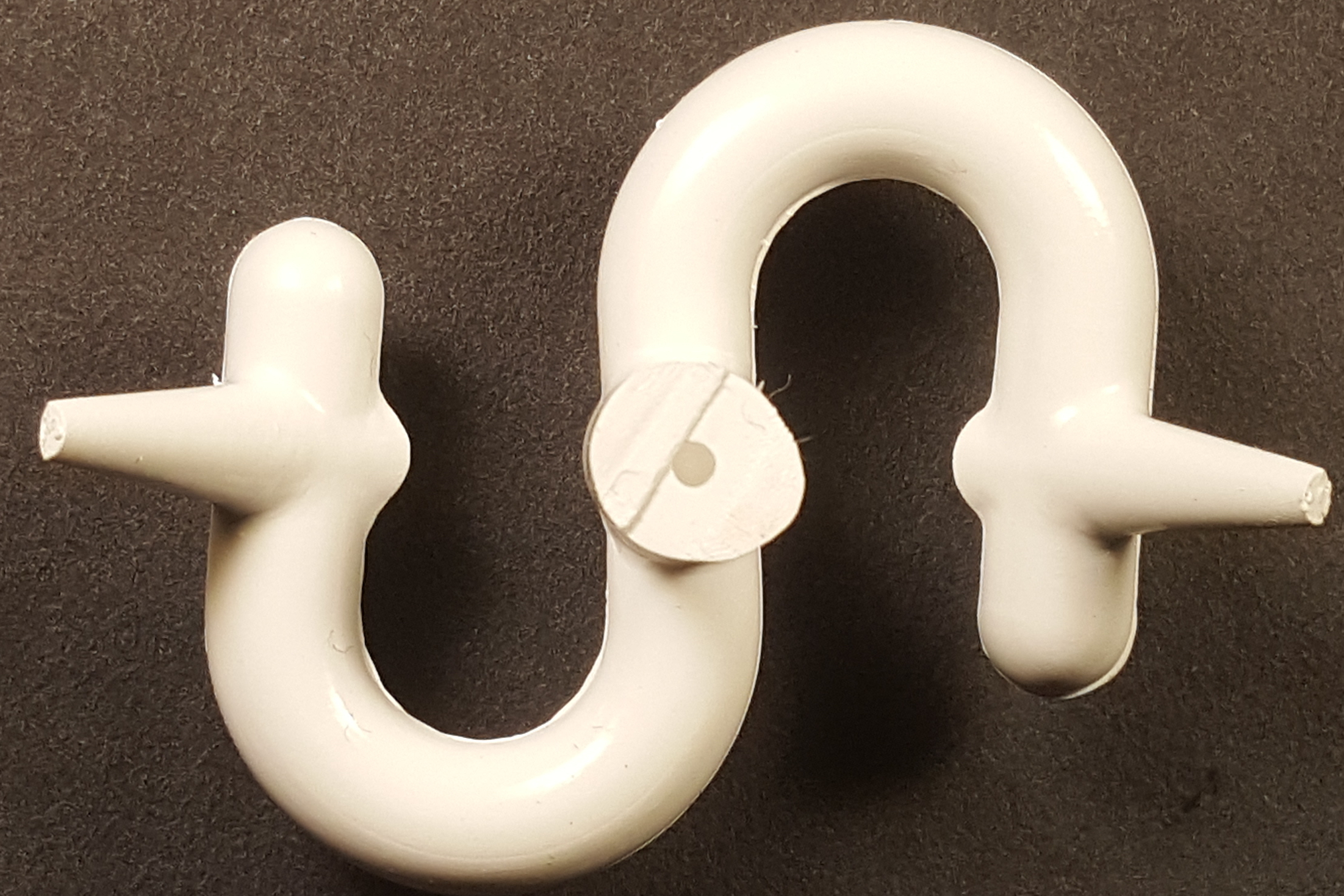
FIG 2 It’s good practice to have the runner perpendicular to the gate.
Ideally, the runner should be perpendicular to the gate, as shown in Fig. 2. Extend the runner past the gate by 1½ times its diameter, the typical length of a runner overflow. Now you have an overflow well to trap any debris in front of the melt flow, and you can add a vent at the end of the runner without sacrificing bearing surface near the gate.
Venting at the End of Fill
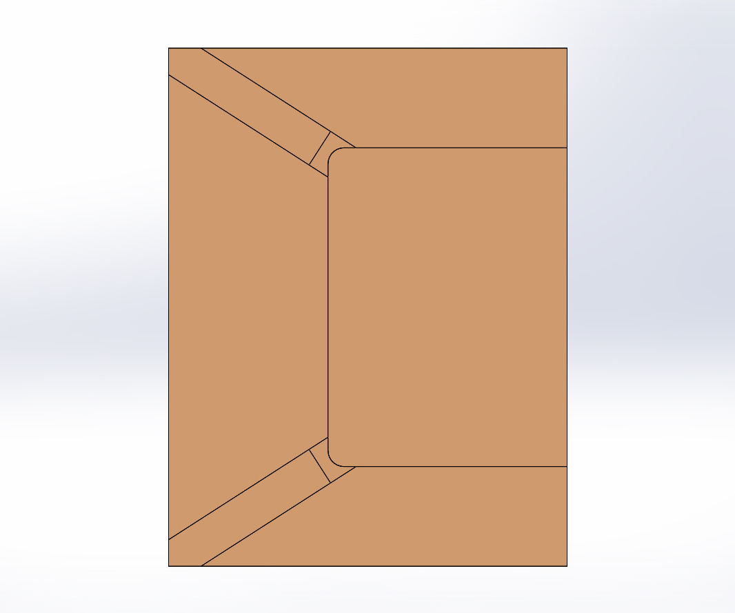
FIG 3A Typical corner ventin
There is yet another rule of thumb: “Always vent at the end of fill.” That’s a good general rule, but don’t take it literally. Let’s say you have a mold making a simple edge-gated, dart-impact plaque. The standard practice is to put a vent in each of the two corners opposite the gate — the last places to fill, as shown in Fig. 3A.
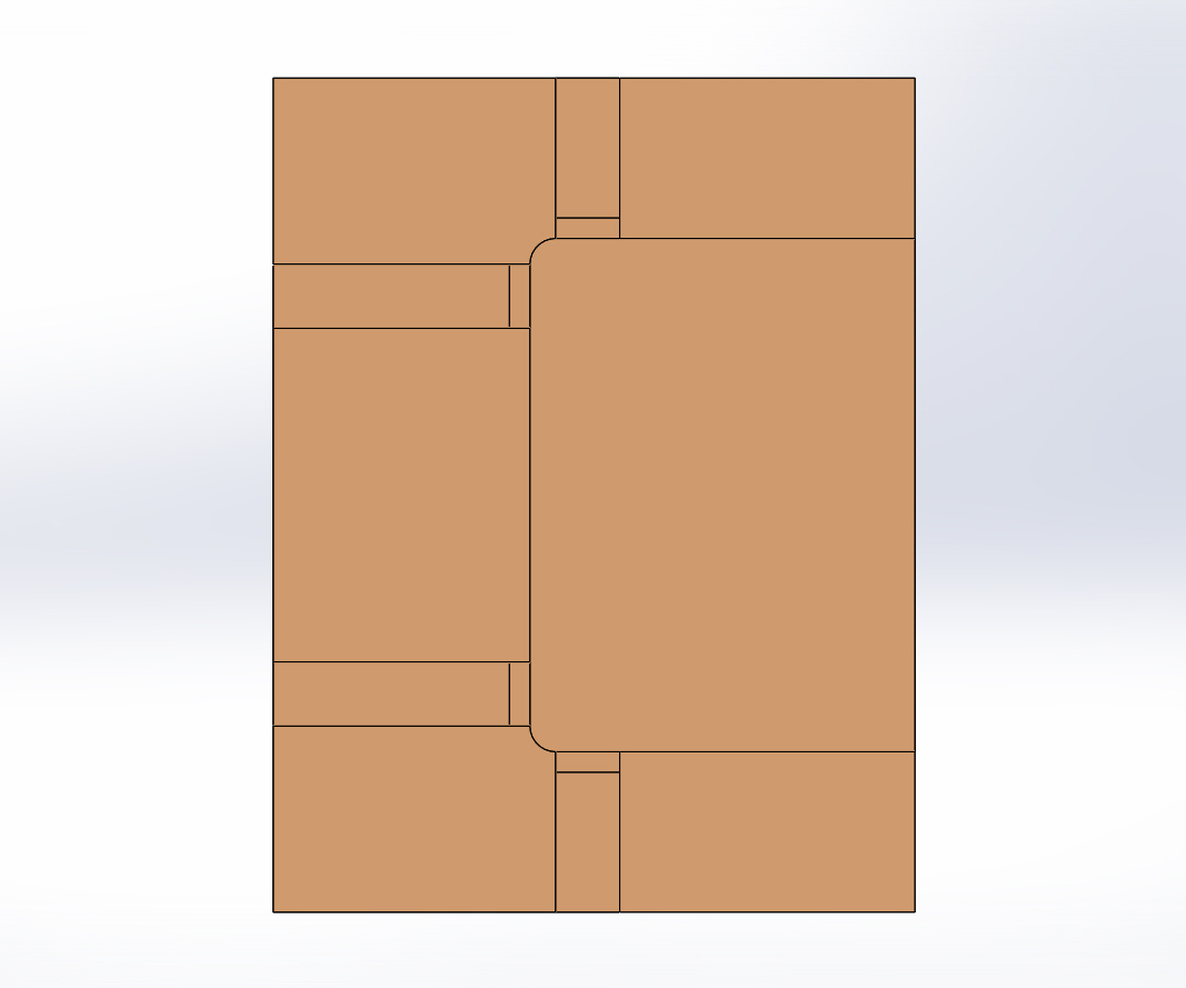
FIG 3B Improved (double) corner venting.
If you look closely at the vent land in Fig. 3A, you can see that it varies in length — shortest in the middle and longer as it goes toward the outer edges. That’s a really bad design. If you want to dramatically increase the life span of corner vents, double the quantity and put them about 1/16 to ⅛ inch away from the corners, as shown in Fig. 3B. If you take into consideration that the last little bit of trapped air in a cavity is usually very compressed, extremely hot and highly saturated with corrosive volatiles, this venting layout will help defer erosion of the vents and the cavity steel.
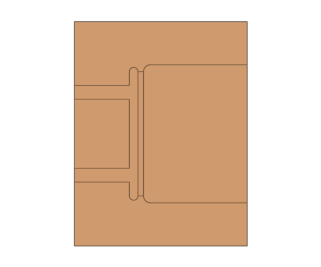
FIG 3C Best (full-length) corner venting.
The best method of venting this type of part (Fig. 3C) is to put a vent along the entire edge, but just shy of the corners. This results in a much greater amount of vent flow area for the compressed air to exhaust through, and still protects the corners.
Figures 3A, B and C depict different examples of “spot” vents. Figure 3C, with a very wide spot vent, leads me to the next type of static or stationary vent, called a continuous or peripheral vent. Quite simply put, this type of vent runs completely, or almost completely, around the entire part. If it’s a round part, some people call this a ring vent. If it’s a square part, some people call this a perimeter vent. It doesn’t matter whether it is round, square or any shape imaginable. If the vent runs around the outer edge of the part, it’s a continuous vent. If there is a small gap between a stripper-plate shutoff and the core, this is also a continuous vent. The purpose of continuous vents is to maximize the airflow area, which is extremely important if the process requires a very fast fill.
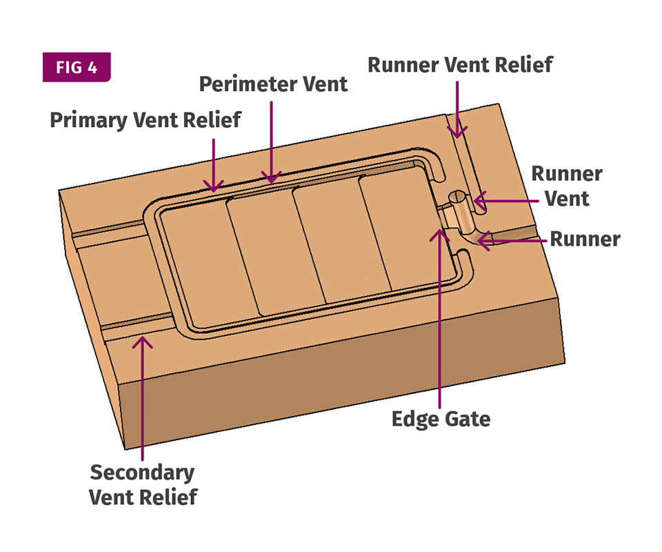
FIG 4 A semi-continuous vent around a color-chip cavity insert.
Figure 4 shows a continuous vent around most of a cavity for a simple color-chip mold. The only place where there is no vent is on either side of the gate. If you can picture how the material flows into the cavity, or if you performed a mold-flow simulation, you would realize that all four corners of the part are locations where air can get trapped, not just the two corners opposite the gate. That is why it is important to add vents in the corners on the gate end, as well as opposite the gate. Also, notice how the end of the runner has a nice wide vent off to its side, as opposed to a narrow vent at the end.
No matter what type of vents you use, follow the guidelines discussed in last month’s article, “Part 2: Back to Basics on Mold Venting” — especially those on grinding and polishing the vents in the same direction as the flow of air.
Continuous vents around the cavity maximize the amount of airflow area.
One location that frequently has a venting problem is at the bottom of a blind rib or other types of freestanding projections, such as a solid or hollow boss. If a projection is more than 1½ times as deep as it is thick, there’s a good chance it will trap air, which can make it difficult to fill or cause the trapped air to “diesel” and leave a burn mark. That’s an important point: It is not the depth that causes the issues; it’s the ratio of the thickness to the depth. With ribs, these problems worsen when they are situated perpendicular to the flow of material.
One of the most common ways to vent a deep rib is to install an insert in the mold. The insert forms a split line adjacent to, or preferably in the middle of, the rib. Some people call this a “natural” vent, which is a vent created by the clearance between any two mold components, such as core inserts, cams, lifters and ejector pins.
Mold inserts are commonly used for deep ribs because it is much easier and less expensive to machine and polish a rib cut into the side of an insert than it is to EDM a blind rib and draw polish it to a fine finish with a thin stone afterward. Another advantage of incorporating a rib insert is that it eliminates the potential for the core to crack, which originates at the bottom of the rib. Ribs have a lot of surface area, and the injection pressure tries to spread the steel apart like a wishbone at Thanksgiving dinner. If the mold is overpacked, an insert will usually shift away from the core a couple of thousandths.
It is for this reason that vents on mold inserts should be on the low side of the material manufacturer’s recommended depth. As the insert “breathes” during injection, the vents get slightly larger. However, you can add multiple vents — or vent the entire width of the insert at the end of fill location — to compensate for the shallower depth.
Options for Keeping Vents Clean
There is a downside to having a split line along a rib: trying to keep the vent(s) clean. Static vents on the parting line are easy to clean in the press. Static vents at the bottom of a deep rib on an insert usually require complete disassembly of the mold. That is why some people prefer to use vented ejector pins at the bottom of a rib. Ejector pins are dynamic or “moving” vents. You can clean a good portion of the pins with the mold still in the machine by advancing the ejector plate fully forward.
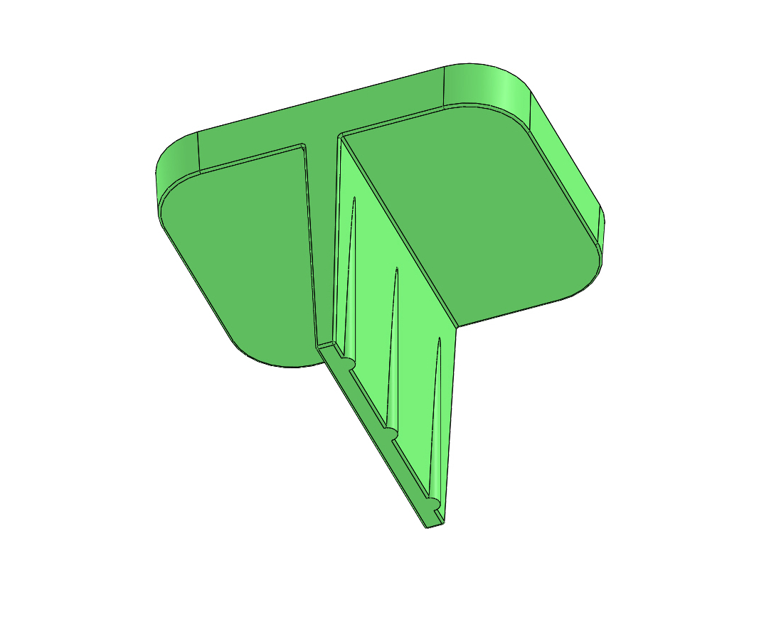
FIG 5 A deep rib with offset KO pins.
Ejector pins at the bottom of a rib are usually a smart idea. Ribs tend to stick in the mold with a tremendous amount of holding force. Ejector pins directly under ribs are about the best method to ensure that the ribs eject under various molding conditions. So how do you decide which way to go — insert the mold to keep the cost down, or keep the core solid and use ejector pins to prolong mold operation before maintenance?
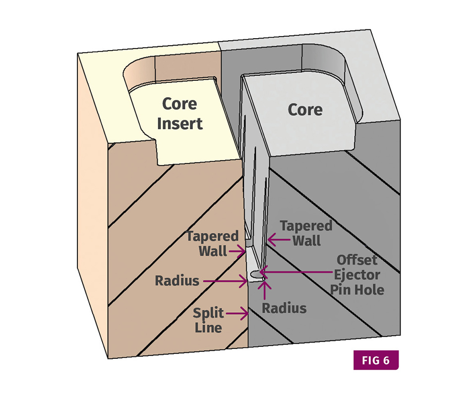
FIG 6 A core insert for a deep rib with offset KO pins.
Why not enjoy the benefits of both methods by combining them together, as shown in Fig. 5 and 6?
Most designers typically locate ejector pins in the center of a rib. That’s fine if the rib is machined in a solid. When using a mold insert, you can’t put the ejector pins in the center of the rib, because a portion of the shaft of the pin will be on the split line. Reducing the ejector pin diameter is a bad solution. Small pins have the nasty habit of galling, seizing, bending and breaking. If you offset the ejector pins, you can stay with the larger diameter. They won’t encroach on the split line, and you have a sufficient amount of steel between the pin and the insert.
Some people refer to vented ejector pins as “self-cleaning.” Similar to stationary vents, they are not self-cleaning. They are self-clearing. Anyone who has wiped the sludge off vent pins while performing a routine preventive maintenance knows this all too well.
Venting at Weld Lines
In the 1947 book, Injection Molding of Plastics, the late Dr. Islyn Thomas summarized the need for a particular vent location better than I ever could. He said, “Vent cavities at weld lines or junction points where two or more material streams meet and fuse into a solid mass. Release of trapped air in those cases will permit intimate contact between converging streams and result in the improved strength and appearance of the molded article.”
That was 72 years ago and it absolutely holds true today. Weld lines and meld lines are formed by converging melt streams. The most common causes of converging streams are: (1) Having two or more gates per cavity; (2) having an opening in the part that material must flow around; or (3) having varying wall thicknesses or an improper gate location, which creates a “backfill” condition.
You can use core inserts anywhere there is trapped air, such as in the case of converging melt streams. They can be square, round or any shape. Even a vent pin, whether it be stationary or dynamic, is a type of core insert when you use it specifically to let air escape. When using a vent pin, do not put the center of the pin in the center of the trapped air location. To achieve the best results, locate an edge of the vent pin at the center of the air trap. When you have two or more gates per cavity, the location of the trapped air can shift a little, due to varying process conditions. You might need to use a large vent pin or multiple vent pins to compensate for this variation.
Vents do not necessarily need to have a path for the air to exhaust out to the atmosphere.
If you can tolerate a small boss on the underside of the part, it is best to recess the vent pin ¼ inch or more. It transforms a weak weld line into a stronger meld line, because the material continues to flow into the boss created by the recessed pin. If the boss interferes with the function of the part, you can contour the recessed pin like a “Z-Puller” for a cold well. Depending on the type of molding material, you can usually snap it off after the part is ejected.
Venting on Shutoffs
If you have an opening in a part, such as in the case of a picture frame, you can add vents to the center shutoff surface in order to exhaust any trapped air on the inner edges of the part. The relief channel(s) on these vents can go to a drilled through-hole in the shutoff. You can also use this vent and relief method on the faces of cams and lifters. Anywhere there is steel-on-steel contact, there is usually an opportunity to add a vent.
Vents do not necessarily need to have a path for the air to exhaust out to the atmosphere. On dozens of occasions, I have used vents that exhausted air into a blind pocket. For example, I once had a ½-inch diameter core pin form a through-hole in a thick part. The material stream naturally flowed around the pin and converged on the opposing side. Venting the outer diameter of the core pin did a good job of exhausting the small amount of trapped air on the bottom of the part, but the top of the part still showed an occasional burn mark.
I drilled a 1/16-inch diameter by ⅜-inch deep hole in the face of the core pin, where it shuts off against the cavity. A vent was ground on the top of the pin, oriented in the direction of the converging material streams. The blind hole was large enough to capture the small amount of trapped air. Every time the mold opened, the compressed air inside the pin was relieved. Blind vents come in very handy when you discover a problem when sampling a new mold. When there’s nowhere to exhaust the air due to a waterline, lifter or some other obstacle, it’s nice to have a plan B.
Reverse Venting
Even if you don’t have a filling or burning issue, venting freestanding projections (whether on the core side or the cavity side) is always a good idea. Air actually flows through vents in both directions. While the more common scenario is for the air to exhaust out of the cavity during injection to prevent filling and burning issues, vents also allow air to enter the cavity during mold opening and ejection. Vents thereby eliminate a vacuum condition that can cause a part or feature to stick in the cavity or on the core.
This vacuum condition can sometimes drive you crazy. Not only can the air pull out of the vent, often the buildup of outgasses comes with it, leaving grease marks on the underside of the part. Still, this reverse venting can enable faster mold opening, as well as reduce the amount of force required to eject the part. In extreme cases, you can feed compressed air through a vent, just as you would with an air poppet valve.
Locate an edge of a vent pin at the center of the trapped air location.
In multicavity molds, not only do you need to vent each cavity the exact same way, you also need to vent every runner branch the exact same way. Otherwise, it can cause an unbalanced fill and pack situation. When it’s all said and done, be sure to update the mold drawings with the final static and dynamic vent locations, widths, depths, types and more. Over time, the vents will most likely wear or collapse. You will need to replace or re-machine them to their original depths.
ABOUT THE AUTHOR Jim Fattori is a third-generation injection molder with more than 40 years of molding experience. He is the founder of Injection Mold Consulting LLC. Contact jim@injectionmoldconsulting.com; injectionmoldconsulting.com.


Related Content

How to Design Three-Plate Molds: Part 5
There are many things to consider, and paying attention to the details can help avoid machine downtime and higher maintenance costs. In this installment, the focus is on design and placement of sucker/puller pins.
Read More
Design Your Tools for Moldability ... and Maintenance
In the initial design phase, when considering the structure and elements of the tool, are you designing them to be maintenance friendly? Canon Virginia has used this approach and preventive maintenance to make tool replacement a thing of the past. You can, too. Here’s how.
Read More
Three Key Decisions for an Optimal Ejection System
When determining the best ejection option for a tool, molders must consider the ejector’s surface area, location and style.
Read More
What You Need to Know About Leader Pins and Bushings
There’s a lot more to these humble but essential mold components than you might suspect. Following the author’s tips could save much time, money and frustration.
Read MoreRead Next

Back to Basics on Mold Venting (Part 1)
Here’s what you need to know to improve the quality of your parts and to protect your molds.
Read More
Back to Basics on Mold Venting (Part 2: Shape, Dimensions, Details)
Here’s how to get the most out of your stationary mold vents.
Read More
Lead the Conversation, Change the Conversation
Coverage of single-use plastics can be both misleading and demoralizing. Here are 10 tips for changing the perception of the plastics industry at your company and in your community.
Read More