
INJECTION MOLDING: How Does Your Machine Control Pack Velocity?
You’ll need to find out in order to develop a molding process that you can repeat from machine to machine and mold to mold.
.jpg;width=70;height=70;mode=crop;format=webp)
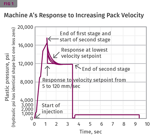
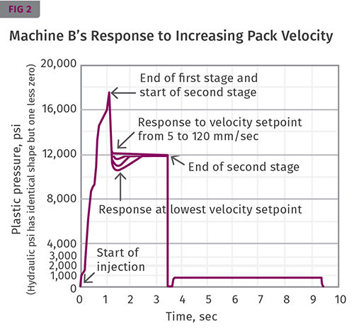
These graphs show the possibilities if the pack velocity is controlled by second-stage pressure. Both figures indicate that the response does not change after a certain relatively low velocity is reached. As shown in Fig. 2, the response is the same from 5 to 120 mm/sec. From 0.1 to 5 mm/sec, the dip gets closer to the flat line; after 5 mm/sec, nothing changes
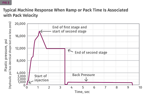
This graph represents a typical ramp time to set pressure—when first-stage set pressure controls the velocity of pack and there is a time associated with it. This can definitely overpack and flash your mold. This type of response is generally not recommended. A rapid drop to the set hold pressure usually provides a more robust process and less mold wear


With the hundreds of variables that can influence your process, machine quirks or characteristics can be right up there helping foul up production. In the May 2014 issue of this magazine, my colleague Kip Doyle highlighted the importance of “Knowing Your Machine” in an article with that title (see link top right). Good molders know the characteristics of the machines they work with.
For example, how does your machine define cushion—minimum screw position or position of the screw at the end of hold? Does it have series or parallel controller logic? With parallel logic, all the injection time, including second-stage pack and hold is in the injection timer, so setting a second-stage time on the controller screen can be meaningless. To find the true hold time, the molder must subtract the actual fill time from the set time on the injection timer. A series-logic controller ignores any remaining time on the injection timer after first stage is reached and provides a second-stage time exactly at whatever is set.


It is not a question of which is better, it is a matter of “knowing your machine” to duplicate a process. There are several of these operating characteristics (or quirks) that distinguish between machines, but here let’s focus on second-stage or pack velocity. This is a processing variable that is controllable on some machines and not on others. What’s even more confusing is that some machines have one input, others have two or even three inputs that can influence what happens.
All machines have a first stage for getting most of the plastic into the part, normally 90% to 99.9% full by volume, and a second stage to pack the part to replicate the steel cavity texture and shape. Second stage or pack-and-hold moves relatively little plastic into the cavity, but how it is done has enormous influence on the process and subsequently the part. So what is the recommend method for establishing the parameters of the second stage?
Most molders focus on establishing two: second-stage pressure and time. In Scientific Molding we determine four, and there is a procedure for each:
1. How to switch over from first to second stage.
2. Whether the part should be run with the gate sealed (frozen) or unsealed.
3. How much hold time is needed.
4. How much pressure is needed to pack the cavity properly.
Second-stage velocity hones in on how to switch over. Controlling switchover from first to second stage is a critical aspect of developing and repeating a molding process, especially as you transfer a mold from one machine to another. It can make or break your process for quality parts, and is often the reason molders cannot duplicate parts on different machines. It is hard to believe a tenth of second can make the difference between good vs. bad parts, but it does. Small part, large part, thin wall or thick—how you switch from first to second stage is key to a consistent process and parts. This must be controlled deliberately by the molder, not a random variable controlled by a machine’s operating characteristics.
To begin, you must understand that the end of the first stage and the beginning of the second stage is a simultaneous point from the controller’s perspective. If you are switching via screw position, the moment the screw reaches that position is when the controller tells the machine to end the first stage and begin second stage. This happens on most machines in 0.001 to 0.003 sec. Next, you need to learn how to “see” what is happening as the machine transfers from first to second stage. This is so fast and subtle that the packing velocity cannot be evaluated or “seen” merely by watching the machine or feeling the injection unit at switchover.
One way to “see” what’s happening at switchover is to use the injection pressure vs. time plot, which is available on most machines. It may take time to get this graphic properly set up, but it’s worth it. It has several uses, but for our purposes it provides graphics of what is happening in the transfer from first to second stage. If your machine does not have the ability to plot this with at least 100 points/sec, you’ll have to look over the shoulder of the controller with a process-monitoring or graphing device.
Once you have the graphics working, to plot injection pressure vs. time, go to the screen on your controller that deals with pack or second-stage velocity. If your machine calls it a velocity, the first thing you have to figure out is what pressure controls this pack velocity—first-stage set pressure or second-stage pressure. For any velocity or speed control to work properly it must have a Delta P, the difference between the pressure used and the pressure available. In other words, you must have some additional pressure available to achieve the set speed.
How to figure out what controls pack velocity and how it works:
1. With the machine running a normal cycle, drop the second-stage pressure to a pressure that minimally packs out the part. Sinks are OK, as you are not trying to make good parts here, just figuring out how the machine works.
2. Go to the graphing screen and note what the graph looks like. Ideally the graph will overlay each shot, but if it does not have this overlay capability, take a picture with your cell phone and store it.
3. Go to the screen that allows you to set the pack velocity and adjust it to the lowest value it allows you to enter.
4. Go to the graphing screen and note what it looks like. Use overlay, or take a picture so you can compare graphs.
5. Adjust the velocity to twice the minimum value, note the graph and continue increasing the pack velocity.
6. Continue until you cover the range allowed, noting graph variations and above all keeping your wits about you to not damage the mold, machine, or yourself.
See Figs. 1 and 2 for possibilities if the pack velocity is controlled by second-stage pressure. Note that the response stops changing after you reach a certain (usually low) velocity. For example, in both figures the response is the same for all velocities, from 5 to 120 mm/sec. This shows you are pressure-limited in the second stage. You really do not have velocity control. All the pack-velocity control can do on these machines is restrict how fast they get to the second-stage set pressure. Machines that provide responses as shown in Fig. 1 may underpack your part if set too low. Machines that provide responses as in Fig. 2 will tend to overpack and perhaps flash your part.
My general rule for machines exhibiting responses as in Figs. 1 and 2 is to set the pack velocity so that it allows the machine to reach a stable set hold pressure in the least amount of time. However, there are processes that will need a special setting. Either way, it is not something to be left to the machine’s default.
For machines that add a “Mode” response—sometimes labeled Sharp, Fine, Soft, Medium, Standard, Mode 1, 2 (or letters)—you have another parameter added to pack velocity. Nearly all the machine manufacturers tend to have different labels for this, which is confusing. As I understand it, this is the response of the servo in milliseconds to achieve the setpoint. I think it would be easier to understand if they just listed the millisecond options available.
For machines that have a “mode” response, my experience has been that you get variations on the graphs in Figs. 1 and 2. Checking out what they really do is the same as described above: Start with the slowest “Mode” and go faster while noting how the pressure vs. time graph changes. There’s no general rule here; I use the response that provides what I need for the particular mold and process.
To further complicate the issue, some machines provide a time for pack velocity or ramp time. Fig. 3 represents a typical ramp time to set pressure, when first-stage set pressure controls the pack velocity and there is a time associated with it. This can definitely overpack and flash your mold. Generally, I do not recommend this type of response. A rapid drop to the set hold pressure usually provides a more robust process and less mold wear.
Not all machines have the same graphics, which is confusing. How about some standardization here? Have three identical screens on all presses, with the rest devoted to the builder’s special effects.


Related Content

Understanding the Effect of Pressure Losses on Injection Molded Parts
The compressibility of plastics as a class of materials means the pressure punched into the machine control and the pressure the melt experiences at the end of fill within the mold will be very different. What does this difference mean for process consistency and part quality?
Read More
Injection Molding: Focus on these Seven Areas to Set a Preventive Maintenance Schedule
Performing fundamental maintenance inspections frequently assures press longevity and process stability. Here’s a checklist to help you stay on top of seven key systems.
Read More
Optimizing Pack & Hold Times for Hot-Runner & Valve-Gated Molds
Using scientific procedures will help you put an end to all that time-consuming trial and error. Part 1 of 2.
Read More
Fundamentals of Polyethylene – Part 5: Metallocenes
How the development of new catalysts—notably metallocenes—paved the way for the development of material grades never before possible.
Read MoreRead Next

INJECTION MOLDING: ‘Know Your Machine’
Many molders think they “know their machine,” but in reality do not. They get consumed by the demands of day-to-day production requirements and lose sight of the big picture.
Read More
People 4.0 – How to Get Buy-In from Your Staff for Industry 4.0 Systems
Implementing a production monitoring system as the foundation of a ‘smart factory’ is about integrating people with new technology as much as it is about integrating machines and computers. Here are tips from a company that has gone through the process.
Read More