


Everyone agrees that producing products from recycled PET (rPET) is a good thing, but producing quality parts from a relatively random feedstock like post-consumer PET bottles is not an easy task. A lot of attention is paid—and rightfully so—to the sophisticated process equipment in rPET plants that is used to achieve that goal (e.g., optical sorting, filtration, extrusion, etc.). Unfortunately, the transfer systems that move the material between that equipment are sometimes added as an afterthought, which can result in less than optimal overall plant performance.
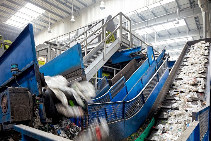
In a PET recycling operation, what ties all the process steps together is the conveying system—so it should be designed specifically for this material. (Photo: ALPLA)
System Design
Keeping a plant running starts with a good-quality plant design, and not all transfer equipment is equal. A screw conveyor that worked really great for the past decade on the chip line will most likely be undersized and fail quickly on a flake line. The pneumatic transfer equipment that can move 10,000 lb/hr of chip might be able to move only 4000 lb/hr of flake. A common pitfall is not following design guidelines developed specifically for handling recycled materials.


The pneumatic transfer equipment that can move 10,000 lb/hr of chip might be able to move only 4000 lb/hr of flake.
The most basic idea to consider is that the low bulk density of PET bottle flake reduces a transfer system’s actual capacity when compared with higher-bulk-density granular materials. Flake is also more irregular in shape. This means that equipment for handling flake is generally large. Screw conveyors for PET chip may be half the diameter and use motors that are two-thirds the power of those designed for flake. A pneumatic transfer system that can move 6000 lb/hr of chip through 3-in. pipe will need 31/2-in. pipe for flake. A solids-to-air ratio of up to 15:1 can be used for chip, but it is best to operate flake systems at a maximum of 5:1 ratio.
Can you use the same conveying-air pickup velocity for flake that worked fine for uniform-shaped pellets? No, it will be too low for getting irregular flake moving. In storage bins, the 60° cone that lets pellets flow out easily has to be a tall 70° cone for flake. Depending on the size of the storage container, bin activation might be needed to get flake to flow. Most of these “rules” are developed by trial and error, so rely on an engineer that has experience designing processes specifically for rPET flake.
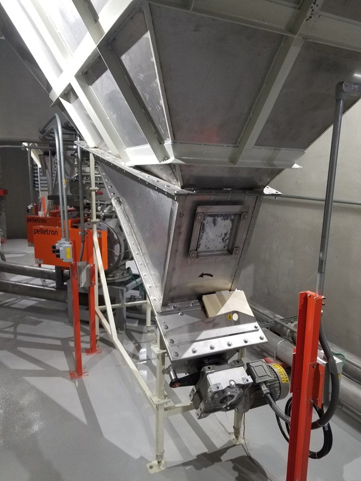
Some traditional flow aids for bulk solids are not enough for bottle flake. The bin outlet shown here is aided by an inclined screw that breaks up bridges and discharges flake into a rotary airlock for reliable and steady feeding into the pneumatic conveying system.
Wrong Components
A good conveying system design does not guarantee that the system will be reliable. To achieve reliable performance, the components within a transfer system have to be designed specifically for rPET flake.
Rotary valves that feed flake into a pressure-conveying system or into any other part of the process must be heavy-duty to withstand years of abuse from the irregular flake and all the other contaminants that pass through them. Heavy cast stainless-steel housings and rotors certainly cost more than thinner sheet-metal designs, but that extra cost is offset by reduced downtime and reduced hardware replacement costs.
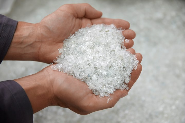
Recycled PET flake is not the same in particle shape or bulk density as PET chip. It’s also quite abrasive. (Photo: ALPLA)
Rotors in rotary valves designed for flake should have a V-shaped rotor and a “plow” in the inlet to reduce chopping and jamming. Flexible tips are sometimes used to overcome chopping problems, but these tips require constant maintenance and also introduce small metal fragments into the process that can be problematic downstream.
Elbows in pneumatic transfer systems are a common headache since flake is abrasive. Flake transfer systems have relatively high velocities, and the flake that slides along the outside surface of the elbow will wear through schedule 10 stainless-steel pipe. Specialty bends to minimize this problem are offered by a variety of suppliers and can even be made by mechanical contractors.
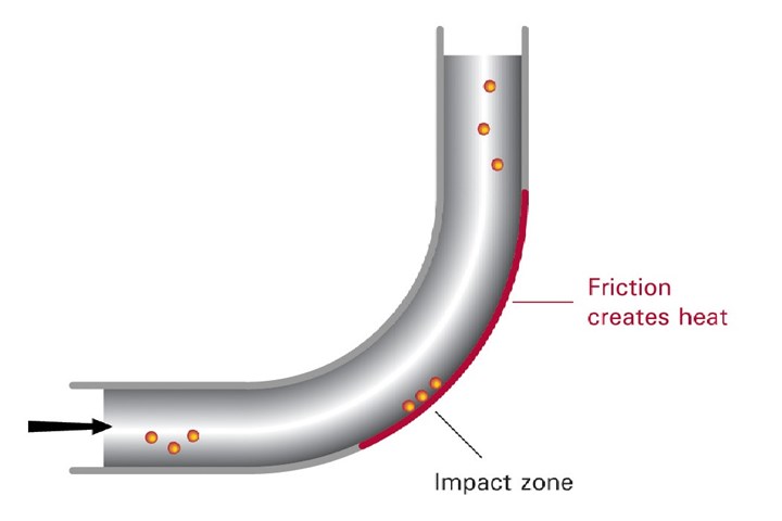
Wear occurs in regular long-radius bends because abrasive solids slide along the outside surface at high speeds. Consider using the fewest bends possible and perhaps using specialty bends that are designed to reduce this wear.
Plan Your Maintenance
Creating and executing a maintenance plan for a plant’s transfer systems is the final step, since there are numerous moving parts that are exposed to direct contact with irregular flake and contaminants. Unfortunately, planned maintenance is commonly overlooked.
Some rotary airlocks have shaft seals that require constant tightening so they don’t leak. Look for valves with labyrinth shaft seals and outboard bearings that don’t require periodic maintenance. These valves usually require shaft-seal purging with clean instrument air when they are used in flake applications. Make sure the shaft-seal purge pressure is set correctly (generally around 5 psig higher than the maximum conveying pressure) and make sure the air is actually flowing.
Worn rotary-valve rotors can cause excessive leakage from positive-pressure conveying systems. This leakage reduces the transfer-air volume in the pipe, which can reduce the total capacity of the system. It also can cause bridging problems in hoppers above the rotary airlock, so inspect the clearance between the rotor tips and housing periodically.
Worn rotary-valve rotors can cause excessive leakage from positive-pressure conveying systems.
Air filters that clean the conveying air before releasing it back to the atmosphere clog quickly in rPET plants because of the high dust load. Make sure differential pressure gauges are working properly and make sure operators check them periodically. Very light and fluffy PET dust can clog or bridge the outlets of dust collectors, but high level transmitters in the discharge cone can help detect these clogs before they cause a bigger problem. Make sure that the accumulated dust inside of bag-house style dust collectors are cleaned out periodically.
This article can’t cover every rule of thumb for reliable design and maintenance of transfer systems in rPET plants, but hopefully you take away that there are many points to consider and there is no substitute for experience. Consider following the recommendations of equipment suppliers that have references for handling rPET flake in the past. Those vendors have been through all of the trial and error so you don’t have to go through them too.
ABOUT THE AUTHOR: Joseph Lutz is the director of sales & marketing for Pelletron Corp. He has 15 years of technical experience developing bulk material-handling solutions for plastics. His career at Pelletron began in R&D, where he learned the ins and outs of pneumatic conveying in the test lab. Lutz has commissioned numerous pneumatic-conveying systems all over the world and earned three patents for new products. Contact: 717-381-3437; joseph.lutz@pelletroncorp.com; pelletroncorp.com.


Related Content

A Recycling Plant, Renewed
Reinvention is essential at Capital Polymers, a toll recycler that has completely transformed its operation in a short period of time.
Read More
‘Monomaterial’ Trend in Packaging and Beyond Will Only Thrive
In terms of sustainability measures, monomaterial structures are already making good headway and will evolve even further.
Read More
Calculating an Injection Molding Machine’s Carbon Footprint
Arburg has utilized the ISO TS 1467:2018 standard, which determines the greenhouse gas emissions of a product, to help its customers calculate the product carbon footprint (PCF) of its injection molding machines.
Read More
Avoid Four Common Traps In Granulation
Today, more than ever, granulation is an important step in the total production process. Our expert explains a few of the many common traps to avoid when thinking about granulators
Read MoreRead Next

How to Ensure Reliable Feeder Performance When Handling PCR
Processors are being challenged to incorporate more recycled material into their products. Yet there are both economical and technical obstacles to achieving this objective—feeding among them. The design of your feeding equipment and the advantages that it will offer to your process will be more important than ever.
Read More
How and Where Twin-Screw Extruders Fit in Recycling
When utilized in a thoughtful way, the corotating intermeshing twin-screw extruder can transform recycled materials into value-added products and parts. Here’s what you need to know, and some real-world examples of the technology deployed for both post-industrial and post-consumer recycling.
Read More