
Molding Simulation: New Frontiers in Process Prediction
Software suppliers agree that 3D simulation of injection mold filling, packing, cooling, shrinkage, and warpage is fairly mature.

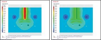
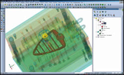
The latest 3D software programs are tackling a broader range of molding concerns. Moldex3D R9.0 has a new Optics module (left) that predicts flow-induced birefringence in the filling, packing, and cooling stages. Moldflow’s new MPI 6.2 (right) contains an interface to Code V optical design software to determine how the molding process affects lens quality.
Another focus of simulation development is rapid heat/cool cycling of molds for thinwall and/or highly cosmetic parts. Moldex3D’s new Transient Cool module for simulating this “variotherm” process reportedly helps produce large parts like LCD TV frames without visible weld lines.
Moldflow’s brand-new MPI 6.2 contains an Advanced Gate Locator that can simultaneously identify up to 10 potential gate locations while avoiding any areas prohibited for structural, cosmetic, or other reasons.
New functions in brand-new VISI Flow 16, coming out this month from Vero Software, save time by automatically analyzing a 3D mold design and generating a mesh on the runners and cooling channels.
Closer integration of CAD and simulation within the same software environment in the new VISI 16 CAD/CAM/CAE suite provides a faster way to make part and mold design changes without returning to the original CAD file and reduces the number of steps between design, analysis, and mold machining.
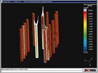
Newest Sigmasoft 4.6 simulation software contains ejector simulation, which determines optimal ejector location and models part deformation during ejection.
Software suppliers agree that 3D simulation of injection mold filling, packing, cooling, shrinkage, and warpage is fairly mature. Their latest releases focus on bringing new or enhanced capabilities to computer modeling of more sophisticated processes like multi-material molding, micro-molding, or rapid heat/cool cycling of molds. Software developers also seek to model a wider range of phenomena such as birefringence in optical parts, warpage in gas-assist or thermoset molding, long-glass orientation, or the stresses and deformation imposed on parts by ejector pins (see front cover of this issue). New versions of simulation software also offer users new ways to optimize gating type and position, model hot- and cold-runner systems, and more.
Other themes include the integration of 3D simulation functions into broader packages of CAD, mold design, and/or machining. Improved interfaces between the software and downstream structural analysis packages are also prominent in several new modules. Recent advances in math algorithms have yielded new abilities to model both the viscous and elastic properties of polymer melts, thereby eliminating some previous assumptions made by the software. And a brand-new type of solid mesh element is said to improve modeling of parts around the gate area. Also, a new micro-mechanics model calculates the properties of fiber-filled materials.


New solvers deliver results faster and new software utilities make the task of simulation easier, from managing projects with new virtual workspaces, to automatic mesh-healing and STL-repair tools, and “wizards” that ease moldbase selection or cooling design. There are also enhancements to simplified simulation packages designed for a quick check of manufacturability.
All the four major suppliers of injection simulation software have news to report. They are Moldflow, Coretech of Taiwan (which nowadays prefers to be known by the name of its software, Moldex3D), Vero Software, and Sigma Engineering. Although there are a number of common themes, their news is reported here on a company-by-company basis, in part because users tend to be dedicated to one supplier’s products.
NEW HELP WITH GATING
Moldflow, the leading supplier of 3D simulation technology, introduced several new developments in its flagship simulation software, Moldflow Plastics Insight (MPI), version 6.2. To start with, it has more horsepower. 3D filling and packing analyses take on average half as long as before with the new AMG matrix solver, especially with larger models. And the latest Dual Domain solver creates the mesh faster so as to save 5% to 10% of the overall project time.
New algorithms are said to make gating decisions easier by identifying gate locations that will produce the lowest injection pressure. The new Advanced Gate Locator offers more capabilities than the older gate locator, which is still available for faster but less refined gating analysis. The Advanced Gate Locator is available for 3D analysis (unlike the former version), as well as mid-plane and Dual Domain modeling. The new locator can simultaneously recommend up to 10 gate locations and can rule out specific regions of the part geometry that have been prohibited by the user. “Regions that should not be used for gating because of aesthetic, tooling, or other reasons can be excluded before starting the analysis by selecting specific nodes on the model that are designated as prohibited nodes,” says Murali Annareddy, director of product marketing.
The Advanced Gate Locator lets the user specify a minimum thickness ratio in order to exclude gates from very thin regions. Users now can also set gate sizes. Previously, the locator assumed a gate size of 2 mm for standard molding, 1 mm for thermosets, and 0.1 mm for underfill encapsulation.
MODEL COMPLEX PROCESSES
In conventional injection molding, the mold is maintained at nearly constant temperature throughput the molding cycle. However, there has been growing interest lately in techniques that use a variable mold temperature. The mold is at first hotter to facilitate filling of thinwall or micro-textured parts and/or to achieve a smoother surface. Then the mold temperature is lowered quickly for packing and cooling. Moldflow addresses this interest in its new MPI 6.2 version, which allows variable mold surface-temperature profiles to be set up for use in Fill and Pack analyses.
Moldflow also addresses the enormous growth in popularity of multi-shot molding processes. Complex overmolded parts can position the various material components in numerous configurations. Previously, only a limited subset of these configurations could be properly simulated for warpage using 3D meshes. An improved algorithm in MPI’s 3D Warp now establishes contact between all components in two- and three-material overmolding applications, including inserts. The improved algorithm is better able to tolerate small gaps between the meshes on different overmolding components. This is particularly important when working with components that have curved contact surfaces between them, where it can be challenging to ensure perfect contact between the meshes. Supported configurations include an insert that is in contact with both the first and second components of a two-shot sequentially overmolded part, and an insert encapsulated exclusively within the first or second shot.
BETTER RESIN MODELING
Moldflow also rolled out a new micro-mechanics model that provides more accurate shrinkage and warpage predictions of fiber-filled liquid-crystal polymer (LCP) materials. The new model is much better able to capture the anisotropic nature of LCPs, Moldflow says, and this significantly improves the calculation of mechanical properties for this special class of materials, which are often used in electronic connectors. The new model can be used with all three Moldflow analysis technologies (midplane, Dual Domain and 3D).
MPI 6.2 also has a new 3D Warp solver for unfilled materials with anisotropic mechanical properties. In previous releases the material was treated as isotropic and thus the orientation effects were not accurately predicted. “Until now the software could not determine the anisotropy with unfilled materials. It just averaged the properties,” says Annareddy. The Warp solver no longer makes this assumption.
Moldflow has extended the Pack and Warp analysis for thermoset materials in its MPI products and Moldflow Plastics Advisers (the latter designed for quick manufacturability analysis). Moldflow now can simulate the packing, shrinkage, and warpage characteristics of thermosets for reactive molding and microchip encapsulation processes using not just 3D analysis as before but also with midplane and Dual Domain analyses.
Moldflow also added venting analysis for 3D reactive molding and microchip encapsulation processes. Users can now assign a vent location, vent size and exit pressures. Previously, the mold was assumed to have perfect venting. “This could cause up to a 20% error in pressure drop, since there is no accounting for the high-shear region or dead flow,” say Matt Pooley, MPI project manager. Users can now edit vent properties, similar to assigning coolant entrance properties. Users can see vent region pressures and pressure build-up in non-vented areas to determine if a vent is adequate or even needed. The venting analysis calculates the air-pressure build-up in the unfilled cavity, based on the venting locations and sizes, and accounts for the influence of the air pressure on the filling pattern.
In other warpage-related developments, part designers working with gas-assist can now evaluate the effect of hollowed-out gas channels on the overall part warpage. Moldflow’s 3D Warp analysis with gas assist can take advantage of the parallel-processing capabilities of newer multiprocessor computers. MPI 6.2 also adds an “Isolate Cause of Warpage” option.
MPI 6.2 offers the new ability to assign a 3D Cold Runner element property to tetrahedral mesh elements. This allows the 3D Warp solver to identify which elements belong to the part and which to the cold-runner system and thereby exclude the cold runner from the warpage analysis. This improves the accuracy of warpage predictions and reduces analysis time.
PLAYS WELL WITH OTHERS
Moldflow has improved the integration of its simulation software upstream with CAD programs and downstream with finite-element analysis (FEA) of molded part performance. Updated Moldflow Design Link (MDL) software allows for the direct import of solid geometry from CAD into MPI or MPA. The new MDL 6.0 version can seamlessly import native CAD data from a wider range of CAD programs and has a new mesh generator that directly generates Dual Domain or 3D meshes that are “analysis-ready.” MDL handles multi-material applications as well, simultaneously meshing all material components and ensuring that contact surfaces of mating materials are matched. This feature is said to result in time savings.
MDL software now generates 3D meshes directly from the CAD file. Previously, an intermediate Dual Domain mesh was created and then remeshed into 3D. Eliminating this step improves user productivity.
In addition, since CAD software supplier Autodesk recently completed its acquisition of Moldflow, closer integration of Autodesk and Moldflow products can be expected.
New types of information are available to Moldflow users through integration downstream with FEA programs. A new data-export option allows results from MPI 6.2 simulation to be used in the HyperStudy design/process-optimization program from Altair Engineering. By linking MPI and HyperStudy, design engineers have a powerful tool to gain insight into the robustness of a plastic part design and can perform trade-off and optimization studies to balance performance and manufacturability. Resizing of runners and geometry optimization to build flow leaders that balance mold filling and minimize clamp force and/or part distortion are examples of how this technology can be used.
A new interface between MPI and Code V optical design software from Optical Research Associates allows MPI results to be used to investigate how the molding process affects the optical properties of lenses.
SIMPLE ANALYSIS ADVANCES
Moldflow Plastics Advisers, designed for fast, simple analysis of manufacturability, is out in an MPA 8.1 release with new visualization options that allow comparison of results from multiple analysis iterations. Users can compare analysis results from two or more models by synchronizing result selection and view orientation. An Overlay function simultaneously displays a combination of two results. And a new Dynamic Help function helps users quickly understand the results that have the greatest impact on optimizing part and mold designs.
A cost adviser function in MPA that facilitates a part-cost analysis has been redesigned in the new version. Association with the model allows evaluation of how changes to part design, mold design, material choice, and processing conditions affect part cost. It will track these changes automatically and display the current cost based on material usage, cycle times, operating costs, post-molding costs, and overhead.
A new Advanced 3D add-on module for MPA 8.1 enables analysis of part geometries with thick solid regions or abrupt changes in part thickness, both of which are not usually suited to the Dual Domain technology of MPA, which is geared more to thin-wall parts. This Advanced 3D analysis, used together with the Performance Adviser and Cooling Circuit Adviser, can evaluate warpage and cooling for thick, solid models.
There are also enhancements to the cooling and runner modeling tools. A new Runner System Wizard produces a complete feed system automatically based on user-defined sprue, runner, and gate properties. Users have the flexibility to manually create gates of different types and cross-sections. MPA 8.1 also has new tools that help speed layout of runners and cooling channels. For example, new Snap Tools let additional runner segments or cooling baffles and bubblers “snap” into place along an existing runner or cooling circuit. Runner and cooling channel layouts now also can be exported for reuse in a CAD system.
NEW PERFORMANCE MODELS
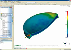
Moldex3D (represented here by EPS Flotek) has new developments and enhancements concerning viscoelasticity, cooling, and multi-material and optical molding. The company says it is the first to offer a 3D model that predicts flow-induced residual stresses by simulating the melt’s elastic behavior in addition to its viscous behavior during processing. “Many agree that this should be implemented, but until now the computation time and memory required made it impossible,” says Venny Yang, president of Moldex3D. The software predicts the flow-induced stress near the mold surface, which occurs from rapid freezing of elongated polymeric chains during filling. Flow-induced stress also may develop in the center of the flow channel near the gate due to additional shear flow during packing.
“In the past we had to make an assumption. We took the maximum shear stress from the flow calculation and used it as an index for residual stress. This indirect method did not reveal how much stress would be relaxed during the packing and cooling phase, or in which areas the stress would be relaxed more or less. So the realization was not the most efficient,” Yang says. Adding a viscoelastic variable to the calculation lengthens computation time and memory requirements significantly. Yang says the added computation time is still acceptable “for those who care about flow-induced residual stress.”
This development has allowed Moldex3D to create an optics module, since it can now calculate optical properties based on the residual stress. And the firm’s Solid-Warp module can import the results as the initial stress condition in calculating the effect of flow-induced residual stress on warpage. The residual-stress calculation can also be used to predict potential part cracking or cosmetic problems in painting.
MOLD THERMAL CYCLING
As with Moldflow, Moldex3D has come up with simulation technology for so-called “variotherm” processes in which the mold temperature is rapidly cycled from hot to cold to hot for thin-wall or highly cosmetic parts. The new Transient Cool module gives improved time-dependent mold and moldbase temperature history compared with the previous SolidCool function. The previous version only predicted the high/low temperature limits and could not “see” the true temperature variation through the mold, says Yang. Now, the mold-temperature data is interfaced with filling/packing simulation so that the effect of mold temperature on melt flow can be considered. The new module supports a wider range of mold-temperature-control options, such as steam heating. According to Yang, the variotherm software can help produce large parts like LCD TV frames with no visible weld lines.
The software now supports sensor nodes in the moldbase to monitor the mold temperature history. The new Transient Cool module can predict heat transfer between a part and an insert in a multi-material molding process. Also, reheating of inserts during overmolding can be visualized. Transient Cool takes the mechanical properties of overmolded and substrate materials into consideration to predict warpage.
PREDICTING BIREFRINGENCE
Among improvements in the latest version (R9.0) of Moldex3D is a new Optics module that predicts flow-induced birefringence in the filling, packing, and cooling stages. The module considers polymer fluid flow, heat transfer, viscoelasticity, photoelasticity, and a stress-optical law to investigate birefringence in optical parts molded of materials such as acrylic, PC, and COC (cyclic olefin copolymer). The optical module can model parts up to 8 mm thick at the center and 0.2 to 0.5 mm at the edges. Yang says digital projector lenses, currently made with glass, are an application ripe for conversion to plastic. Polymer lenses are less expensive to produce and have a lower scrap rate. With optical glass, 80 out of every 100 made are thrown away, Yang notes.
In thermosets, the Solid-RIM module has a new curing model for polyurethane and can be used with the multi-material molding simulation that was new in the previous version, Moldex3D R8.1.
Moldex3D R9.0 has also upgraded features of the main modules that are used across its range of products. The Designer module has a new STL file-repair tool that helps users remove most STL defects automatically. It has the same power as the surface mesh auto-repair function in Moldex3D-Mesh. There is also a new moldbase wizard with a more user-friendly interface for moldbase design, as well as a new cooling-system wizard that allows for quick layout of cooling channels. In addition, a new coolant entrance/exit wizard finds optimal inlet/outlet positions for coolant and adds them automatically to the cooling system. A new cooling-system “doctor” checks whether the cooling system is well defined or not. It shows information on the detected trouble spots and offers solutions.
Moldex3D Project has been enhanced to help users better manage their work. It has a new rotate and translate control for clipping and slicing a solid model more easily. A new automatic image-capture function gathers and lists all the results, such as geometry model, mesh quality, filling pressure, warpage displacement, etc.
The Moldex3D-Mesh module includes an improved automatic mesh-refinement function that identifies many more geometry characteristics and provides a more refined mesh-size control, which helps to balance the mesh quality and quantity. The module now fixes points of poor mesh visibility and poor-quality solid elements in complex areas of a model. The mesh-repair function has been improved significantly and fixes most solid elements in minutes.
Yang says the Moldex3D solid modules now can export all of the simulation data into Ansys or Abaqus FEA structural analysis programs to determine mold deformation, core shift, part reliability, and part fatigue. Moldex3D previously transferred just the anisotropic properties, but now everything can be exported. “If you have a mold in Abacus and want to predict how much the cavity pressure affects mechanisms in the mold like sliders, you can now import pressure history into the structural-analysis program and use the pressure history to estimate the effects,” says Yang, who adds that this is still in the initial stages.\
A new set of solid elements designed to improve meshing around the gate is in development, Yang says. The new elements, planned for the next version (Moldex3D R9.1), are applied in a special patent-pending meshing technique. The next version will also have a new OneButton function that launches 3D analysis from all major CAD systems with one click. The function transfers all necessary data from the CAD model into the simulation system and makes it ready for analysis.
Moldex3D has several enhancements in its eDesign Module, an easy-to-use solid-modeling program for quick moldability validation of thick or thin parts. The software is part of Moldex3D R9.0 and is based on the same platform but is designed for simpler operations. The software takes 3D CAD geometry to analysis results in a few simple steps and can be used to optimize gate locations, prevent short shots and weld lines, evaluate cooling circuits, and minimize cycle times. The eDesign mesh now supports multi-material molding and valve gating for the first time.
INTEGRATION WITH CAD
One of the biggest developments from Vero is the planned release this month of its newest 3D flow simulation software, VISI Flow 16, as a fully integrated module of the new VISI 16 suite, which includes VISI Modeling, VISI Mold, and VISI Machining. Says VISI Flow application engineer Vijay Kudchadkar, “This enables the user to design the part completely from scratch in VISI Modeling and make changes to existing parts, design, mold, analysis and/or manufacturing.”
Vero, a supplier of CAD/CAM software for mold and die makers, acquired the 2.5D and 3D simulation technology of Plastics & Computer of Italy. Integrating the simulation software, renamed VISI Flow, eliminates translation issues between CAD, simulation, and machining software within the VISI suite. Users of just the VISI Flow products can use direct translators to import files in common CAD system formats or STL files.
Among several recent improvements to VISI Flow 16 are improved mesh generation that allows the user to make changes without having to go back to the CAD model. “The integrated software brings the CAD and flow simulation environments closer together. Users can track all of their changes because they stay in the same environment now,” says Kudchadkar.
Also new in VISI 16 is 3D mesh generation on mold plates and inserts, which now can be brought into the analysis. Users can assign a mold material to each plate for more accurate thermal analysis.
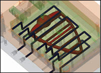
New Runner-To-Flow and Cooling-To-Flow functions automatically analyze a 3D mold design and generate a mesh on the runner diameters or cooling channels, saving setup time. The mold design can be built in VISI Mold or imported from an external CAD system.
The mesh-generation feature of VISI Flow has been enhanced with a new algorithm that improves the uniformity of the triangle elements and reduces the number of elements required. The new capability to mesh local areas of the model brings the user the possibility to describe small features better.
Other enhancements include the automatic calculation of part thickness, a new interface that simplifies managing every part of the runner system, and faster layout of runner and cooling systems due to full integration with VISI.
Kudchadkar notes that new 3D modules for gas-assist and coinjection are included in VISI 16, coming out this month, and 3D overmolding and thermoset (including LSR) programs will follow. A new way to model hot-runner tip geometry (a longstanding challenge) is also being developed. This software will create an integrated mesh of the hot-runner nozzle and tip.
HOT RUNNERS & EJECTORS
New developments in the areas of hot-runner modeling and ejector simulation are the latest advances in Sigma Engineering’s Sigmasoft software. The company, which focuses software development on 3D thermal simulation rather than 3D filling, says the Sigma 4.6 version, released last fall, now has the PI (Proportional Integrated) controller fully incorporated into its hot-runner module. This means that the “thermal inertia” of each heating zone in the sprue, manifold, and bushings is automatically assessed and the subsequent P and I coefficients are determined. The coefficients are determined by “virtually” heating up the mold in the software and analyzing how it cools down again. Sigma runs the virtual heat-up/cool-down cycle three times to determine the exact temperature distribution. “Accurate temperature distribution can be used for multi-cycle simulations in the flow, pack, shrinkage, and warpage stages. A hot-runner designer can use the knowledge to decide the best positioning of thermocouples,” says Wim Schermerhorn, director of sales and marketing at Sigmasoft’s headquarters in Germany.
The software also shows what happens behind the melt front during filling, such as what shear-heating distribution develops in the runner system from point to point and how this creates preferential flow paths that can lead to unbalanced multicavity filling.
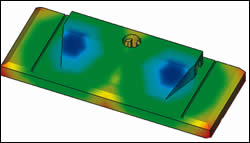
Ejector simulation is also a big focus in the newest Sigmasoft version. Says Schermerhorn, “The program determines where contact pressure develops between the cavity wall and the solidifying part. It also simulates stress relaxation while the part is still in the mold. Users can determine where and how a part is going to stick in the mold, and with an accurate relaxed stress distribution, we can now perform a reliable ejector simulation that shows which ejectors are doing the brunt of the work and which ejectors are not contributing at all.”
The new simulation also shows whether the area of the part where the ejector pushes is stiff enough to take the ejector loading or not. “This gives the user insight into when the part has achieved suitable stiffness, instead of using only temperature criteria,” says Schermerhorn. It is a full-contact simulation that shows temperature distribution and internal stresses. The software can show how the ejectors push the part from the mold and cause deformation. The module can show the difference that a flat or a contoured ejector will make.
Sigma also developed a new Second Heat Cycle module, designed to model products such as housewares that are prone to deform during initial heat exposure after molding. “Manfacturers mold the part and then put it on a fixture, which is placed in an oven with a light heat cycle to relax the stress,” explains Schermerhorn. This provides confidence that the part will not warp or distort in the customer’s use. The software assesses what is needed for the fixture, shows how much stress will fall off during the heating cycle, and whether a longer or hotter cycle is required.
Sigma is also focused on improving its materials data for more accurate shrinkage or warpage simulation by using Poisson’s Ratio to calculate data that has not be been directly measured. The company found that it could use Young’s Modulus and PVT data to determine the Poisson’s Ratio as a function of temperature. “Using this approach and three stress/strain curves for three temperatures is one road to more accurate shrink/warp measurement,” Schermerhorn adds.
Sigma continues to work on a module to simulate long-glass fiber orientation and will release a module for powder injection molding within a year. The company also plans to enhance its micro-molding module, scaling down the model to provide fast but accurate predictions.


Related Content

Netstal To Introduce Next-Generation All-Electric Elion Injection Molding Machines at K 2025
Netstal will introduce the Elion MED in Düsseldorf with a smaller footprint and greater energy efficiency.
Read More
Medical and Molding Elite
When Jeff Smith received a notice evicting his promising business out of his house, it could have been the end of Elite Biomedical Solutions’ and Elite Precision Plastics’ stories before they really got started, instead it was just the beginning.
Read More
Sumitomo (SHI) Demag Plans for ‘Electric’ K 2025
Debuts include an all-electric multicomponent IntElect 350t combined with a SAM-C20 robot and two high-speed PAC-E machines targeting high-speed packaging applications.
Read More
No Platens, No Problem: Mold-Masters and Partner Mold Without Press at K 2025
The fully integrated cell molded medical parts from a side-gated hot runner system without the platens, tie bars and mold open/close normally associated with injection molding.
Read MoreRead Next

3D Molding Simulation Growing in Accuracy & Capabilities
New developments in 3D simulation can handle processes like gas assist, coinjection, and multi-shot molding and add features like birefringence prediction.
Read More
Mold Analysis Gets Faster, Easier, Smarter
On Dec. 28, Moldflow Corp. began shipping a major new release of its flagship injection mold simulation software, Moldflow Plastics Insight 6.0.
Read More
People 4.0 – How to Get Buy-In from Your Staff for Industry 4.0 Systems
Implementing a production monitoring system as the foundation of a ‘smart factory’ is about integrating people with new technology as much as it is about integrating machines and computers. Here are tips from a company that has gone through the process.
Read More