
Put the Brakes on Resin Conveying Speed to Minimize System Maintenance
Here’s how to manage pneumatic conveying speeds to extend equipment life and reduce material waste in your plant.
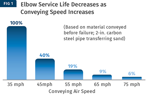
Higher speeds create faster erosion, with a dramatic decrease in relative service life from 35 to 45 mph. As a coarse rule of thumb, the relative service life drops by about half for every 10 mph increase in air speed.
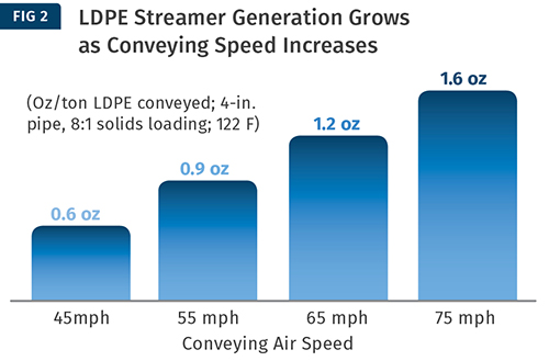
Here, streamer generation increased linearly through the range of speeds, assuming a consistent level of material loading in the conveying line. Using 45 mph as a baseline, streamer generation increased an additional 55% for every 10 mph increase in air speed.
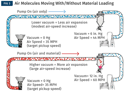
When air molecules move without material loading (top), less vacuum is needed, so the air is "stretched" less and accelerates to a modestly higher speed. When material is added (bottom), every foot of tube, every change of direction through elbows, and every pellet being carried create more resistance to air moving. This steadily growing resistance is overcome by increasing vacuum to keep air and pellets moving. This elevated vacuum "stretches" the air even further, so the air moves much faster as it reaches the pump.
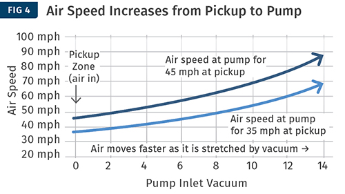
Higher vacuum leads to proportionally higher air speeds downstream and at the pump. A lower pickup speed keeps the downstream increase to a minimum.
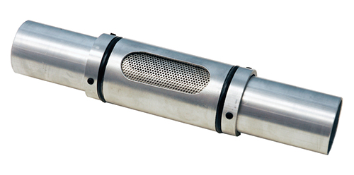
When overall air speed is reduced, the system vacuum may need to be reduced to ensure enough air speed at the pickup. This can be done at the material source pickup probe by rotating the collar to pull more air through the screen, so less material enters the conveying line.
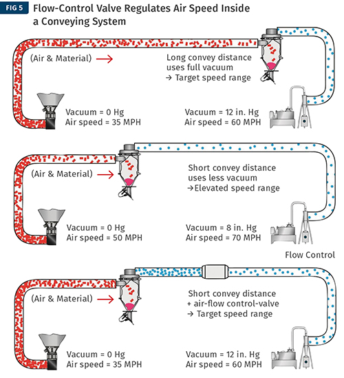
A flow-control valve acts like a governor on the air speed inside a conveying system. When system resistance drops, the valve adds the resistance back into the system, so vacuum and air speed remain steady in a targeted range. When the system resistance is already high and the system air flow is near the design target, it allows the air to pass through unimpeded


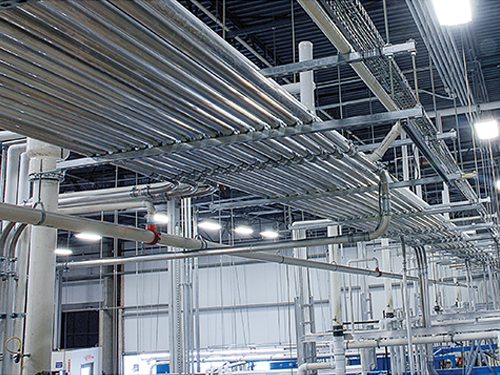
Moving bulk plastics from storage to process through pneumatic conveying tubes is common in most processing plants and has been for decades. But times and materials are changing, and what worked in the past isn’t always enough for reliable results today.
One key issue processors face is the problem of erosive wear of conveying tubing, bends, and other equipment subjected to abrasive materials. Unexpected part failures can create costly repairs and unplanned downtime. This is a growing problem due to expanded use of glass and mineral fillers for improved part performance.


Another common problem is attrition, or degradation of sensitive raw materials. This is often the byproduct of conveying heat-sensitive materials like LDPE or dried acrylic. These materials can soften during conveying, smearing inside the conveying tube surface. This causes buildup that can contaminate other materials or lead to streamers and angel hair that block material flow. Other materials can break easily during conveying, leading to excessive dust, plugged filters, and waste.
These issues may sound like polar opposites, but in reality, both are largely a function of conveying velocity. As material moves faster, particles generate more heat, friction, and impact force, all of which contribute significantly to attrition and wear issues.
Velocity Effects on Elbows & Material
While it’s customary to use feet per minute (fpm) when discussing air speed in a conveying system, this article uses miles per hour (mph) to more easily relate to everyday experience. For added context, we’ll consider two examples of speed-related conveying issues.
The first issue is erosive wear of elbows. Figure 1 illustrates how conveying speed affects elbow life when transferring abrasive materials. As expected, higher speeds create faster erosion, with a dramatic decrease in relative service life from 35 to 45 mph. Continuing through the range of expected conveying speeds, the actual drop in service life is less dramatic, but as a coarse rule of thumb, the relative service life drops by about half for every 10 mph increase in air speed.
The second example of velocity-related conveying issues results from material degradation. Figure 2 illustrates how conveying speed affects streamer generation when transferring softer, heat-sensitive materials—LDPE in this case. Once again, higher speeds contribute to increased problems. Streamer generation increased linearly through the range of speeds, assuming a consistent level of material loading in the conveying line. Using 45 mph as a baseline, streamer generation increased an additional 55% for every 10 mph increase in air speed.
Clearly slower is better to avoid these problems. Unfortunately, there is more happening inside a conveying system than meets the eye.
Understanding Velocity in A Vacuum SYSTEM
Picture a drag race. The light tree turns green and the dragster goes from zero to 30 in a heartbeat, then continues to accelerate faster and faster down the track, throttle wide open to the finish line.
Pellets in your conveying system are like a dragster on the strip—starting from a standstill at your source, then accelerating faster and faster all the way to your receiver.
The vacuum pump is like the engine at full throttle, pulling the material ever faster. And the harder it pulls, the faster it moves everything down the line toward it. The pump’s “pull” is the vacuum it draws, measured in inches of mercury (in. Hg).
As vacuum increases, air is essentially being “stretched” farther and farther apart, or expanding, as it moves from the source toward the pump. The top graphic in Fig. 3 illustrates air molecules moving without material loading. Less vacuum is needed, so the air is “stretched” less and accelerates to a modestly higher speed.
The bottom graphic in Fig. 3 adds material loading. In this case, every foot of tube, every change of direction through elbows, and every pellet being carried create more resistance to air moving. This steadily growing resistance is overcome by increasing vacuum to keep air and pellets moving. This elevated vacuum “stretches” the air even further, so the air moves much faster as it reaches the pump.
Speed Zones in Conveying Systems
The area where material enters the conveying line is often referred to as the pickup zone. For a conveying system to work, air in this area has to move fast enough to sweep the pellets into the airstream from a standstill.
The acceptable speed range in the pickup zone is approximately 35-45 mph. The required speed varies depending on material properties such as bulk density, particle size, and surface friction, but for most plastic pellets, the minimum speed, or pickup velocity, is around 35 mph.
Figure 4 shows how much air speed increases in a conveying system. When a pickup speed is chosen, the pump air speed is selected based on the expected operating vacuum. A higher vacuum “stretches” air more, which requires higher air speeds downstream at the material receiver and at the pump.
Why is this important? As pellets gather speed moving through a conveying system, they become projectiles hurtling toward impact targets like elbows and the receiver/separator. More speed equals more problems, which are typically more prevalent toward the destination rather than the source. We want to target these areas for protection, and when possible, limit the downstream speed to minimize the damage it can cause.
Conventional Design Approach
Designers consider the conveying rate required to keep up with processes, and the physical layout of a given processing plant, to select the required combination of tube size and pump to carry the load. Higher vacuum yields higher conveying rates and improved efficiency for a given tube size. Larger tube sizes carry more material for a given vacuum level.
Many standard pump packages on the market have been selected to provide the maximum rate for the selected tube size by delivering the maximum safe vacuum level. This vacuum, combined with the target pickup air speed, dictates the maximum air speed required downstream at the pump.
To reduce velocity, we might be tempted to choose a conveying tube size larger than needed to reduce vacuum. Less vacuum will “stretch” the air less, and air speed will change less from start to finish as a result. Unfortunately, most standard pump packages already pull air at a preselected speed. If it pulls less vacuum, the unintended result is more speed at the pickup area. And since most standard pumps pull more air when faced with less target resistance, the maximum speed increases as well. More speed at all points in the system leads to more problems with abrasive or sensitive materials.
There are a variety of ways to reduce velocity in a conveying system, some simpler than others, and some more versatile. We’ll consider several methods, starting with the simplest:
• System-wide velocity reduction: A controlled air leak is one of the easiest ways to reduce velocity to all receiver stations in an existing vacuum-conveying system operating above minimum pickup speed. An air leak creates an alternate path for air to enter the conveying line, like a simple bypass. It’s created by adding a series of holes to the vacuum line before the pump safety filter. The size and number of holes, along with operating vacuum, determine the magnitude of the air bypassing the conveying system.
An air leak that’s carefully controlled can reliably reduce system air speed by as much as 30%. But keep in mind that the air leak steals air from the pickup area, so it can cause problems if unplanned or poorly implemented. Symptoms such as material slugging, or a complete line plug, can result when the leak is large and the material loading is high. It’s important to work with a knowledgeable system designer to ensure expected results.
Reducing the pump rpm also reduces air speed across the system, with the added benefit of modest energy savings. If the pump package is belt driven, the sheave combination can often be modified to slow the pump to a new target performance point. If the pump package is a direct-drive setup, a variable-frequency drive (VFD) can be used to select the new target performance point. Once again, a knowledgeable system designer having full application details and pump performance information should be consulted to ensure safe operation and a successful outcome.
When overall air speed is reduced, the system vacuum may need to be reduced to ensure enough air speed at the pickup. This can be done at the material source pickup probe by rotating the collar to pull more air through the screen, so less material enters the conveying line (see photo).
A word of caution when operating at lower vacuum levels, particularly less than 8 in. Hg vacuum: In these situations, the limiting factor can sometimes be the pump’s ability to get a fully loaded conveying line moving from a complete stop, which can exceed the vacuum needed to carry the material once in motion. This is affected a great deal by the system installation, particularly how well the designer managed to avoid material plug areas, such as the arrangement at the base of a vertical tube, or consecutive 90° elbows.
• Controlling velocity variation: A central conveying system often moves material from a common source to multiple points of use. To optimize operation, the material feed rate is adjusted while transferring material to the receiver station farthest from the material source. This is the station that will encounter the most resistance, and the feed rate is adjusted here to achieve the target operating vacuum.
But when the same source feeds another station located a shorter distance away, the system resistance is reduced, and the vacuum level at the pump decreases. Unfortunately, once more, system air speed will increase when vacuum load on the pump decreases, assuming the pump rpm stays the same.
There are two basic methods to address this common variation in air speed. One is mechanical, and the other uses advanced system controls and a VFD.
The simple mechanical approach is a flow-control valve, which acts like a governor on the air speed inside a conveying system. When system resistance drops (think short distance vs. long distance), the flow-control valve adds the resistance back into the system, so vacuum and air speed remain steady in a targeted range. When the system resistance is already high, and the system air flow is near the design target, the flow-control valve allows the air to pass through unimpeded (see Fig. 5).
The flow-control valve is also a good addition to a system that purges the material line empty during each conveying cycle. Purging is often done when conveying dried or blended material from a central location to preserve the material dryness or blend integrity. In a purge system, the resistance in the empty conveying line starts low, then rises to a peak value as material fills the line. When the purge cycle begins, the line gradually empties, and the resistance slowly drops to the lower vacuum level. This natural variation in resistance and vacuum level is automatically corrected by the flow-control valve to guarantee a predetermined maximum air speed for all stations.
• Selecting velocity by station: Advanced conveying controls offer the ability to select a conveying speed for individual stations. A pump speed setting is stored with each station’s parameters, and this setting communicates to a VFD installed with the pump. This flexibility allows the operator to compensate for variations in setup, such as lower rpm and airflow to convey shorter distances and lighter line loads.
The ability to select conveying speed by station adds versatility to handle specific materials differently. General-purpose resins that are less sensitive to velocity effects can be set to move at default speeds to achieve maximum conveying rate. Very heavy materials, or those having poor flow characteristics, may be set to move at elevated speeds. And, of course, stations can be set to lower speeds to minimize material attrition and erosive wear as needed.
These controls sometimes offer speed variation during a single conveying cycle. With this capability, the pump can initially run at full speed to reliably initiate material movement, and reduce the possibility of line plugs or slugging at the start of the conveying cycle. Once material is moving, the pump rpm can be dropped to provide the selected speed for the duration of the fill cycle.
Going one step further, if the material line is purged, the pump rpm can be reduced as the conveying line empties and resistance drops. This reduces air flow as the vacuum decreases, ensuring a maximum speed will not be exceeded.
• Velocity control in long-distance conveying: Conveying materials over longer distances requires more vacuum to achieve a given transfer rate. When rate and distance require vacuum levels from 12 to 15 in. Hg, resulting air speeds are often faster than preferred for both abrasive materials and those sensitive to degradation.
But there is a way to achieve lower conveying speeds at high vacuum and improve your transfer-rate efficiency in the process. Velocity in these systems can be reduced by implementing a dual-diameter conveying line, or stepping the tube diameter to a larger size at a strategic point between the material source and the material destination.
To understand what happens, think of water flowing through rapids, then into a wider area of the stream. The same amount of water flows through each area, but it expands into the larger area and flows more slowly.
In a conveying system, we can take advantage of the reduced speed in the expanded line to increase the material transfer rate substantially under higher vacuum—up to 50% or more added rate versus traditional systems. By maximizing the large-diameter distance, speed decreases, along with resistance to movement, so the pump can carry more material. The key is understanding how resistance builds in the conveying line and how it affects the air speed throughout the entire distance material travels.
Understanding the impact of velocity on conveying system operation can greatly improve your chances for success, especially when moving abrasive plastics and those sensitive to degradation. Selecting the right system, and applying advanced velocity-control methods, will protect your investment, improve system uptime, and reduce maintenance.
In addition to velocity management tools, appropriate component options should be considered to extend maintenance intervals and the overall life of the system. For softer, heat-sensitive materials, using surface-conditioned elbows (shot-peened, spiral-grooved) provides improved protection against streamers and angel hair. For abrasive materials, glass elbows and extended-wear options on receiver stations can extend service life. There are also a number of specialty elbows available that enhance system operation and service life for both of these sensitive material types.
A conveying system is a sizeable investment that can impact a facility’s operations for years to come. Ask your system designer to explain these options and their potential benefits before making your decision.


Related Content

New Pump Rewrites Conveying Rules
NPE2024: Smart Pump technology brings more flexibility and finesse to resin conveying.
Read More
Safety, Recycling, and Compounding Trends Bring New Opportunity to 70-Year-Old Company
NPE2024: Vac-U-Max presents pneumatic conveying solutions for powdered materials.
Read More
AI Comes to Resin Conveying with Conair Technology
This patented technology automatically detects source-to-destination conditions and autonomously adjusts the conveying system in real-time to move material under optimal conditions.
Read More
Industry Vet Duff Joins ACS Group
With 37 years of experience on both machinery and processor side, Michael Duff to handle aftermarket business for auxiliary equipment manufacturer.
Read MoreRead Next

Lead the Conversation, Change the Conversation
Coverage of single-use plastics can be both misleading and demoralizing. Here are 10 tips for changing the perception of the plastics industry at your company and in your community.
Read More
For PLASTICS' CEO Seaholm, NPE to Shine Light on Sustainability Successes
With advocacy, communication and sustainability as three main pillars, Seaholm leads a trade association to NPE that ‘is more active today than we have ever been.’
Read More
People 4.0 – How to Get Buy-In from Your Staff for Industry 4.0 Systems
Implementing a production monitoring system as the foundation of a ‘smart factory’ is about integrating people with new technology as much as it is about integrating machines and computers. Here are tips from a company that has gone through the process.
Read More