What You Need to Know About Blade Ejectors: Part 2
Follow these guidelines to prevent premature wear, flash and galling.


To understand why any two mold components sliding against each other wear and gall, we need to briefly discuss metallurgy. While this may seem boring and technical, it explains why you need to pay particular attention to the types of steel you use in your molds.
Tool steel contains very hard particles called carbides. There are two types of carbides: primary and secondary. Primary carbides are formed when the steel is produced. They are relatively large in size—approximately 40 microns—and they should be evenly spaced apart from one another. Secondary carbides are formed during heat treatment. They are relatively small—approximately 0.5 microns. Steel contains about 5% to 20% of these carbides. The rest of the steel that bonds all the carbides is called the steel matrix. The chemical composition or alloying elements of the steel matrix, along with the carbides is what ultimately determines the steel’s hardness, corrosion resistance, wear resistance and other physical attributes.


When it comes to two components sliding against each other, there are two basic types of wear: abrasive and adhesive. Abrasive wear causes erosion of the metal, typically rounding the corners of contacting surfaces. We intuitively expect that abrasive wear can be minimized by using extremely hard steel. That is not necessarily true because there is a big difference between the hardness of the steel and the hardness of the carbides within the steel that determine its wear resistance.
Think of it as the hardness of the stones in a cobblestone street with mortar surrounding the stones. The mortar is what determines the hardness rating of the steel, but it is the hardness of the stones that determine how well it resists abrasive wear. This is the reason why it takes a lot of time for two sliding components to show abrasive wear.
Tool steel has from 0.5% to over 2% carbon content. It takes at least 0.5% carbon to allow the steel to reach 60 Rockwell C hardness. The excess carbon does not make the steel any harder, but it combines with the other alloying elements, such as chromium, molybdenum, tungsten and vanadium, to make a specific type of carbide within the steel matrix—each having its own hardness value. For example, chromium carbides are about 65 to 70 Rc, molybdenum and tungsten carbides are about 75 Rc, and vanadium carbides are about 80 to 85 Rc.
The amount, type and molecular distribution of these carbides is largely responsible for a steel’s abrasive-wear resistance. They are also responsible for how difficult a steel is to grind or machine. So, now you have an idea about what type of steel to choose if your only concern is abrasive wear. But this article focuses more on adhesive wear, which causes galling and catastrophic failure of ejector blades and other mold components.
Adhesive wear, galling and seizing happen quickly.
Adhesive wear and, ultimately, galling are prevalent when the combination of friction and a compressive force pushes two components together. It is one of the most common causes for ejector blades to fail. Unlike abrasive wear, adhesive wear and then galling happen quickly in a localized area and then spread rapidly outward from their origination point. The ASTM G40 standard defines galling as “a form of surface damage arising between sliding solids, distinguished by macroscopic, usually localized, roughening and creation of protrusion above the original surface; it often includes material transfer, or plastic flow, or both.”
This occurs when the crystalline structure of the softer component starts to slip and tear. Some of this material breaks free and deposits or fuses onto the harder mating component. That’s galling. When these deposits are taller than the clearance between the two sliding components, that’s when they seize. To minimize the risk of galling you need to minimize friction, ductility and cohesive attraction of the metals by doing the following:
1. Use steels with dissimilar material composition and that are known to have low cohesive attraction to one another.
2. Purchase steel from reputable sources. How well the steel is made is just as important as its type.
3. Heat treat one, if not both, components. The harder the steel is, the less ductile it is.
4. Use reputable heat treaters and supply them with the steel’s brand name and specifications.
5. Minimize the surface roughness of the mating components. A polished surface will have smaller “peaks,” which encourage galling by generating frictional heat.
6. Keep the components lubricated during production, which greatly reduces friction.
7. Keep the components clean because dirt and debris increase friction.
8. Consider applying a surface coating or surface treatment to increase the surface hardness or reduce the coefficient of friction of at least one of the components.
An ejector blade must be made of a different type of steel than the component it rides in.
Deep Dive into Galling
The best gall-resistant types of steel have a high concentration of the small secondary carbides. The worst gall-resistant steels have a high concentration of the larger primary carbides. Test data has proven that gall resistance is also influenced by the distribution of both types of carbides. Uniform distribution prevents the carbides from forming into groups or clusters, which promote galling. This is the reason why the manufacturing abilities of the steel supplier are so important. A good supplier will ensure an even distribution of the carbides within the matrix. A good distribution is also why many of the new powdered-metal alloys have excellent wear and galling resistance, because they have smaller sized carbides with exceptional distribution.
There is a process called Electro-Slag Remelting (ESR) that is used to refine steel, giving it smaller carbide particles with better distribution. Unfortunately, this process is expensive and currently only used on a few tool steels, such as H-13 and 420 stainless, but it is good to know about ESR when selecting what brand of steel to use for your cores, cavities, and other mold components.
The best gall-resistant tool steels are O-6, under the trade name Graph-Mo; and A-10, under the trade name Graph-Air. They contain graphitic particles with inherent lubricity and are very good at retaining applied lubricants. Achieving a high concentration of graphitic particles requires very long annealing time—days, not hours. I am told that Timken Steel, then later Latrobe Specialty Metals, and now Carpenter Technology Corp. discontinued offering their Graph-Mo and Graph-Air products—unless you want to purchase over 40,000 lb of them.
Reportedly, the demand for these two brands dwindled due to the higher production costs, and possibly because our industry was not fully aware of their tremendous benefits. O-6 Graph-Mo was replaced with CarTech 06. It has slightly different percentages of alloying elements and very different heat-treating specifications. Carpenter’s A-10 is not even listed on their website anymore. Despite all of this, O-6 and A-10 are still very good materials—regardless of the manufacturer, because they still have some graphitic particles in the matrix. They are just not as good as the original Graph-Mo and Graph-Air once were. Other relatively gall-resistant steels are M-2, O-1, O-2, D-2, and S-1.
Among the least gall-resistant steels are stainless steels. Stainless steel rubbing against stainless steel has extremely high cohesive attraction and is twice as likely to gall as most other steel combinations. Since stainless steel has such a high chrome content, never mate it with steels that also have a high chrome content, such as D-2, H-13, M-2, or S-7. If you are in the medical industry and have stainless-steel molds, you are probably very familiar with galling on nitrided H-13 ejector pins and sleeves. Steels that are better suited in sliding applications with stainless are O-6, A-10, O-1, and M-2.
Stainless steel is twice as likely to gall as most other steels.
It has been proven that hard, heat-treated materials are more resistant to galling because of their lack of ductility, but they are not necessarily immune to galling. Hard surface coatings such as CVD, PVD, TiN, TiCN, and DLC help prevent adhesive wear or galling by uniformly increasing the surface hardness or by reducing the coefficient of friction. It is worth noting that most surface coatings perform better when applied to a highly polished surface. Keep in mind that oil-based polishing compounds can contaminate the surface of the steel, which must be thoroughly cleaned prior to any surface treatment.
What’s Nitrocarburizing?
There is a specialized type of nitrocarburizing case hardening that is starting to make its way into our industry after a long track record of success in other industries. It is a cost-effective quench-polish-quench (QPQ) process with trade names such as Melonite, Tuffride and Tenifer. It is used on carbon steel, stainless steel, alloy steel, and austenitic steels. It is a three-step process: nitrocarburize ("quench"), polish, and post-oxidize ("quench").
The process starts with standard salt-bath nitrocarburizing, where nitrogen diffuses into and chemically combines with nitride-forming elements in the metal. It produces a thin case of tough, ductile compound or “white” layer about 0.0008-in. thick. This hard compound layer has wear properties that are 200% to 1000% greater than the original material, as well as greatly enhanced resistance to corrosion, galling and scuffing.
Below the thin compound layer is a region called the diffusion zone, where nitrogen and carbon are dissolved into the base metal. This zone is about 0.0080-in. thick. The diffusion zone contributes several additional benefits. There is enhanced fatigue strength, typically by 20% to 100%, as well as reduced adhesive wear and anti-seizing properties. After nitriding, the workpiece is mechanically polished. Lastly, the component is re-immersed in the salt bath, or post-oxidized to create a 0.0004- to 0.0010-in. thick, corrosion-resistant, iron oxide (Fe3O4) layer, which gives it a black surface finish.
Surface coatings and treatments perform better when applied to a highly polished surface.
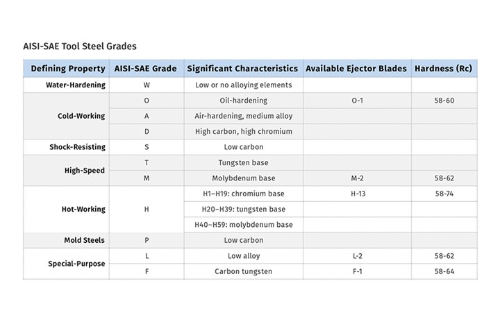
Ejector blades are commercially available in various types of tool steel, such as M-2, O-1, L-2, F-1, and H-13. These are all alloy tool steels, but they belong to five different property families, as shown in the accompanying table. How is a mold designer supposed to know which type is best for a particular application?
A lot of research has been done regarding the compatibility of tool steels when it comes to wear resistance and galling for the sheet-metal forming and stamping industry, but very little has been done for the injection mold industry. While there is an interrelationship between the two industries, there is not enough definitive and quantitative information available for mold designers to select the best types of materials to use in their tools. They are left to rely on their own experiences, or the opinions of others, such as mold-component suppliers, who all say their products are the best.
One would hope that in the near future, a university will be given a grant from one of our trade associations or from some other benefactor to perform an in-depth study on the compatibility and gall resistance of the different types of mold steels, heat treatments, surface finishes, etc. so this mystery can be laid to rest, and countless time and money can be saved.
What About Straight-Sided Interlocks?
It is worth evaluating what steel types, hardnesses and surface treatments are used on straight-sided interlocks. After all, they are sliding surfaces with a lot of side load, which accelerates wear and galling. They just don’t slide as far as ejector blades and other mold components usually do. It has been proven that the amount of wear on sliding components is proportional to the distance they travel and the speed of travel. The amount of wear can therefore be reduced by minimizing the ejection stroke and minimizing the ejection and retraction speeds, as well as the number of ejection pulses during production.
Most of you are probably familiar with the old rule of thumb that components which slide against one another should be made of different types of steel and have a minimum Rockwell C hardness differential of 10 points. This is a very generalized and somewhat misleading rule. While the hardness differential between sliding components is important, it has been proven that having two different types of steel is equally, if not more, important to prevent galling.
The hardness of commercially available ejector blades ranges from 58 to 62 Rc for through-hardened blades and up to 74 Rc for nitrided blades. Cores are often made of H-13, S-7 or 420 stainless with Rockwell C hardnesses ranging from 48 to 54. Therefore, commercially available ejector blades are usually made of a different type of tool steel and they are significantly harder than the heat-treated mold components they ride in. While you may be thinking this is the ideal scenario—different steel types and different hardness’s—that’s not necessarily true.
As with any two components that rub against each other, the softer one will almost always wear first. Since it is a lot cheaper to replace a worn ejector blade than it is to repair a slot or a hole in a worn mold, it stands to reason that the ejector blade wearing first would be preferred. Unless you are going to make your cores out of a very hard, very wear-resistant and very expensive material like CPM-10V or have them coated with a very hard material such as DLC (diamond like coating), the core is going to wear out before the ejector blade does—and that can be expensive over the lifespan of the mold.
It’s actually quite simple to make your own ejector blade and blade holder assembly.
My father realized this fact five decades ago and insisted that all his ejector blades be custom made of spring-tempered 1095 steel with a Rockwell hardness of 48-50. In addition to being a different type of steel with a lower Rockwell hardness, the blades had dramatically higher yield strength and flexibility, which is helpful when a part gets stuck in a mold, allowing the blade to flex instead of cracking.
Depending on the application and type of mating steel, I have had good success with ejector blades made of O-6 steel at 60 Rc. However, I have often been tempted to make blades out of one of the new beryllium-free copper alloys with a 40 Rc hardness. If you think about it, a lot of leader-pin bushings and guided ejection bushings are made of copper and they rarely, if ever, seize up. The softer copper blade will obviously wear faster—which is good. Copper alloys have an inherent lubricity and very high thermal conductivity, which reduces the rate at which it wears. High temperatures caused by friction promote galling. Copper alloys help disperse that heat— over five times faster than tool steel. Unfortunately, I have yet to test this theory. However, I have used a copper alloy as a guide for opposing dovetailed lifters, which has over a million cycles on it with absolutely no galling.
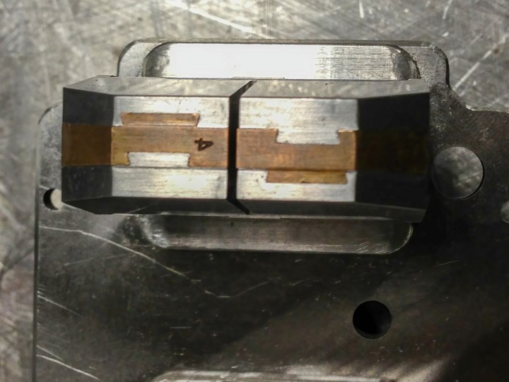
A copper alloy core with opposing dovetailed lifters has run over 1 million cycles with no galling.
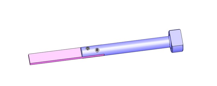
If you don’t want to spend the money for a custom-made ejector blade or prefer to use a different type of steel than is commercially available, it’s actually quite simple to make your own (see illustration). Slot the end of a through-hardened core pin to create a blade holder. Then braze or silver-solder an ejector blade in place. Alternatively, you can cross-drill one or two holes for a spring pin.
Another advantage to making your own blade ejectors is that you can have your ideal width and thickness, as opposed to having to choose from a limited selection in a catalog. You can even make a curved or custom-shaped blade, as opposed to a rectangular one. Making your own ejector blades also allows you to have the shoulder length perfectly suited to the ejection stroke, which minimizes the unsupported length of the blade.
About the Author: Jim Fattori is a third-generation molder with more than 40 years of experience in engineering and project management for custom and captive molders. He is the founder of Injection Mold Consulting LLC in Pennsylvania. Contact: jim@injectionmoldconsulting.com;
injectionmoldconsulting.com
Related Content

How to Set Barrel Zone Temps in Injection Molding
Start by picking a target melt temperature, and double-check data sheets for the resin supplier’s recommendations. Now for the rest...
Read More
Are Your Sprue or Parts Sticking? Here Are Some Solutions
When a sprue or part sticks, the result of trying to unstick it is often more scratches or undercuts, making the problem worse and the fix more costly. Here’s how to set up a proper procedure for this sticky wicket.
Read More
Density & Molecular Weight in Polyethylene
This so-called 'commodity' material is actually quite complex, making selecting the right type a challenge.
Read More
Understanding Strain-Rate Sensitivity In Polymers
Material behavior is fundamentally determined by the equivalence of time and temperature. But that principle tends to be lost on processors and designers. Here’s some guidance.
Read MoreRead Next

Tooling: What You Need to Know About Jump Gates
Many molders don’t care for jump gates because they have to process around them. But here are some tricks of the trade.
Read More
Tooling: The Lowdown on Guided Ejection Systems
When, where, how and why to use them.
Read More
What You Need to Know About Blade Ejectors: Part 1
Follow these guidelines to prevent premature wear, flash and galling.
Read More