Tooling: The Lowdown on Guided Ejection Systems
When, where, how and why to use them.


When you install guide pins and guide bushings within the ejector housing, it is called a guided ejection system. Guided ejection systems greatly increase the longevity of a mold—but they also increase the cost. So, when are they needed and when are they not?
In order to answer that question, we need to define what benefits a guided ejection system provides. The short answer is that they support, guide and align the ejector plates, which in turn supports, aligns and guides the return pins, ejector pins, sleeves, blades, lifters, and any other connected component.

A guided ejection system prevents gravity from transferring the weight of the ejector plates onto the connected mold components. That is the support function of the system. They will also help prevent the ejector plates from cocking and binding, which is often caused by the machine ejector rods not being the exact same length, or an off-center ejection pattern (as a result of an off-center sprue bushing), or a non-symmetrical ejector pin layout (more ejector pins on one side of the mold than the other). That is the guidance function of the system. Most importantly, they ensure that the ejector pins, sleeves, blades, etc. are in the proper location and will move forward and backwards perfectly parallel with the centerline of the mold. That is the alignment function of the system.
Guided ejection systems increase the longevity of a mold.
To help better understand the mechanics of something, I was taught to think in terms of extremes. With that in mind, the ejector plate and ejector retainer plate in a standard 35-1/2 in. × 23-3/4 in. mold base has a combined weight of 350 lb. Without a guided ejection system, that 350 lb is supported by the components connected to the ejector plates. This will cause the ejector pin through holes in the cavity to elongate, which will create “down-flash” on the molded parts. It will also increase the odds of the components galling, seizing, buckling, and prematurely wearing. Bottom line: a guided ejection system helps prevent rejected parts, downtime and mold repair costs.
So, the answer to when a mold should have a guided ejection system is based on four primary factors: 1) the desired lifespan of the mold (in cycles); 2) the weight of the ejector plates; 3) the quantity and complexity of the ejection components; and 4) the hardness of the core inserts. I have seen many unguided aluminum molds have ejection and flash issues in a very short period of time. I don’t know if the lifespan of the mold was projected to be fairly short, or if the driving factor was to keep the mold cost low. Regardless of the reason, flash and wear problems started to occur around 25,000 cycles.
Some moldmakers believe that the return pins adequately support the ejector plates. That belief is almost always incorrect. If you have ever been on a seesaw, you know about mechanical advantage. The forces are even on both ends when the pivot point is in the center of the seesaw. But the closer the pivot point moves towards one of the ends—making its length shorter, the more mechanical advantage is achieved by the longer length on the opposite side.
Guided ejection systems support, align, and guide the ejector plates.
Now if you think about return pins in a mold, the pivot point is at the end of the bearing surface—not too far from the parting line. The entire weight of the ejector plates is on the other end of the pin. The greater the distance between the ejector plates and this pivot or bearing point, the more mechanical advantage there is—and considerably more force than 350 lb, which can easily cause wear and damage to occur. Molds with long ejector strokes and thick B-Plates have greater mechanical advantage then those with short strokes and thin plates. Therefore, they have a greater need for a guided ejection system. I guess that makes this the fifth factor on whether or not a mold needs a guided ejection system.
Guided ejection is an optional feature from most mold base suppliers. That’s understandable, as well as beneficial. They may have recommended sizes and locations for the pins and bushings, but you have the option to specify the quantity, size, location, and installation method that works best for your mold design.
I reviewed the recommendations and specifications for guided ejection systems from one of the largest mold base suppliers, and I came across some interesting facts. This supplier offered 43 different standard mold base lengths and widths, from as small as 7-7/8 in. × 7-7/8 in. all the way up to 35-1/2 in. × 23-3/4 in. Of these 43 different sizes, they recommended that only three of them contain two guided ejector bushings—the three smallest-sized molds. They recommended using four bushings for all of the remaining sizes. I have never seen a mold with more than four guide pins and bushings, but I imagine very large molds could benefit from using six, maybe even eight.
Even though the diameters of bushings in larger molds are correspondingly larger, in order to support the heavier weight of the plates, you have to consider the location of the bushings in relation to the machine’s knockout pattern. If the distance between the knockouts and the guided ejection bushings is relatively long, you run the risk of bending the ejector plates. If the ejector plates are thin or made of a soft material, you can pretty much count on this happening, because it is not uncommon even with steel plates with the standard thicknesses. Note: This one reason why adding more screws connecting the ejector plate to the ejector retainer plate is often a good idea.
The ability for a guided ejection system to precisely guide and align the ejector plates is based on two primary factors: the length of the bushing, and the clearance between the guide pin and the bushing. Most guided ejection bushings come in two lengths: 1-1/2 in. and 1-3/4 in. The clearance between the guide pin and the bushing ranges from 0.0010 in. to 0.0020 in. If you run the numbers, the maximum angle in the worst-case scenario is a mere 0.076° for the 1-1/2 in. bushing, and 0.065° for the 1-3/4 in. bushing. This gives you a good indication of how precise the through holes and counterbore for the pins and bushings in the mold should be. Line boring all of the plates will help ensure the proper position and alignment.
Despite this high precision, there are occasions where even greater guidance may be required. One common example is when a two-cavity family mold is running only one of the cavities – or when the mold has just one cavity offset from the centerline. Regardless of the machine’s ejector pattern, the resisting forces will try to move the ejector plates on an angle. In cases like this, using longer guide bushings will help prevent any premature wear or galling. It may require a thicker plate, or counterboring the plates to allow the longer guide bushings—which are now sticking out beyond the ejector plates—to travel the full ejector stroke. Note: Don’t think you can prevent this from happening by simply using two offset machine knockout bars. Instead of wearing out the mold’s guided ejection system, you are going to wear out the molding machine’s ejector system instead.
Since a cylindrical guide pin rides in a slightly larger cylindrical bore of the bushing, the contact is linear—not circumferential. Linear contact wears out much faster than circumferential contact. Obviously, the harder the surface of the pin and bushing, the less wear there will be. Standard guide pins are nitrided with a surface hardness of 58 to 62 Rockwell C. Guide bushings are commercially available in solid bronze, bronze plate and self-lubricating. This is where you need to be careful. Several suppliers do not state the hardness of their bushings (which is a pet peeve of mine).
How is a moldmaker to make an informed decision? I also question some of these suppliers’ stated specifications. For example, one supplier says its non-plated solid bronze bushings have a surface hardness of 65 to 74 Rockwell C. Unfortunately, just because it says so in a catalog, doesn’t mean it’s necessarily true. Most guided ejection bushings have a hardness of 90 to 180 Brinell, which doesn’t even come close to the hardness of the guide pin. In fact, they are not even on the Rockwell C scale. If you look around, you can find a supplier that offers hardened steel guided ejection bushings (48 to 50 Rc), with a bronze-plated inside diameter and with internal grease grooves. These are my bushings of choice.
One mold-component supplier recently introduced a guided ejection bushing that employs rows of ball bearings on the inside diameter. Depending on the diameter, there are between six and eight rows per bushing. It’s a unique type of “linear” roller bearing, because the rows of ball bearings are not parallel with the centerline of the bushing. They are on a slight angle. Therefore, instead of a single linear contact with the guide pin, there are dozens of contact points around the perimeter of the guide pin. The ball bearings are hardened to 60 to 62 Rc. This can be an issue since they are typically riding on a nitrided guide pin with the same surface hardness. For this application, it would be better to use an angle pin instead of a guide pin. Most, but not all, commercially available angle pins have a nitrided surface hardness of 65 to 74 Rc.
I have used linear ball-bearing bushings in stripper plate, three-plate, and floating plate molds. They are extremely accurate. The only problem I had was they can work too well, allowing them to move with very little force. They can even “bounce” if the opening stroke is fairly fast, or if the plates are not cushioned at the end of their stroke. That can be a safety hazard and possibly one of the reasons you don’t see them offered by most mold-component suppliers any more.
But ball-bearing bushings are an excellent application for a guided ejector system. The only concern I would have is the need for good lubrication—with oil, not grease. Grease retains dirt and dust more readily than oil, which can affect the bushings’ longevity. As many of you probably know or have experienced, applying grease to a self-lubricating, carbon-plugged bushing can cause it to wear out prematurely. The same issue applies to ball bearings. There is no problem using ball-bearing bushings for medical molds running in a cleanroom environment. For additional information on lubricating guided ejection bushings, please see my October 2018 column.
There are two primary methods for installing the guide pins for a guided ejection system. Each has it’s pros and cons. The first way is to install the guide pins into the back of the ejector clamp plate (or ejector housing if the clamp plate and the rails are welded together), as shown in Fig. 1. This method is a little faster and easier to machine, and is the most common method with B-Series mold bases. It also virtually eliminates the common problem of waterlines, bolts, interlocks, core inserts, etc. being in the way. The downside to this method is that when you remove the clamp plate, which holds the guide pins, there’s no support for the ejector plates. All of the weight is now on the pins. This is usually not a problem if you move the ejector plates to their fully forward position.
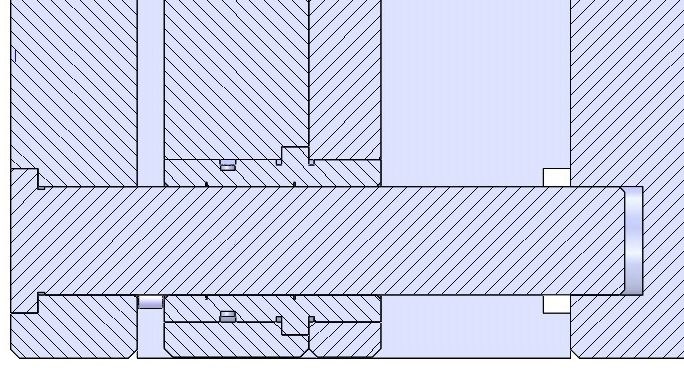
FIG 1 Guide pin in the clamp plate.
There are two primary variations on how to install ejector guide pins.
The other method is to install the guide pins from the front of the B-Retainer plate, assuming it is a laminated A-Series mold base, as shown in Fig. 2. The benefit of this method is that it is easier, faster and safer for the toolmaker to clean the ejector system, replace pins, and reassemble. There is one minor downside to this method. When you remove the clamp plate, ejector plates and ejector pins, the guide pins are still protruding from the back of the B-Retainer plate. This makes it a little difficult to safely flip the mold on its back.
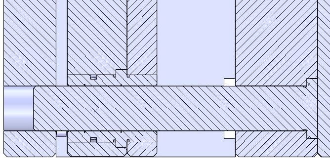
FIG 2 Guided pin in the B-retainer plate.
Almost all guide pins (and leader pins) have an oversized or press-fit shoulder—typically 0.0005 in. to 0.0010 in. over nominal. The length of this shoulder varies by pin diameter and by manufacturer. Keep in mind that depending on the press-fit length, there is potential for it to interfere with the bushing. If it does interfere, simply grind off the required amount of the press-fit area. For those moldmakers who want to make the best of the best, grind off all of the press-fit shoulders and reduce the bore size of the holes they go into by 0.0005 in. You may need to freeze the pins and heat the plate in order to install them, but now the bearing surface is the full thickness of the plate.
There is another issue, which affects both installation methods. Molds are built at room temperature (68 F), but they rarely run at this temperature. For the sake of example, let’s say the mold is 35-1/2 in. × 23-3/4 in. and is running an engineering-grade material at 300 F with hot oil. Ejector plates are typically made of SAE 1030 steel, which has a coefficient of thermal expansion of 6.5 × 10⁻⁶. Therefore, the cavity and core plates will expand 0.036 in. in width and 0.054 in. length. But the ejector plates will hardly expand at all, and there’s a good chance things are going to start to bind up. At the very least, the ejector-pin holes in the cores will start to elongate, and you may never know it until the parts start to develop down-flash.
The way to overcome this potential problem is to use a thicker ejector plate and drill some cooling channels in it. This will equalize the thermal-expansion issue. Additionally, it is best to mount the guide pins in the B-Retainer plate of an A-Series mold base, and provide sufficient clearance in the ejector clamp plate to accommodate the expansion between the guide pins. This way, the ejector clamp plate will not heat up significantly and slowly transfer the heat to the machine’s moving platen. You can also add an insulator plate to the back of the clamp plate. Keep in mind that insulator plates only slow the rate of heat transfer. They do not prevent heat transfer.
Thermal expansion should be taken into consideration.
If the guide pins are installed in the clamp plate, but do not enter into the back of the B-Plate, as shown in Fig. 3, you may not have a thermal-expansion issue between the guide pins and guide bushings, but you will still have the same expansion issue with the return pins, ejector pins, sleeves, blades, etc. Additionally, you lose a significant amount of load-bearing capability when you only anchor one end of the guide pins, instead of both ends.
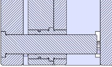
FIG 3 Guided pin supported on only one end.
If you order a mold base with the guided ejector system pre-installed, the bushing will have a slip fit in the front ejector retainer plate and a press fit into the back ejector plate. Many moldmakers would prefer this were reversed. While there is more bearing surface on the thicker ejector plate, it is often difficult (and dangerous) to assemble and disassemble the mold in this condition. If the bushings were press-fit into the ejector retainer plate, the moldmaker can easily remove the ejector plate without the weight of the ejector retainer plate being applied to the ejector pins. There is also less chance of dislodging any small keys or pins used to orient ejector the pins. Whichever way you choose, it is beneficial to add two or four tapped through holes in the ejector plate. You can then screw in standard bolts to separate or “jack” the doweled plates apart. This is a much more delicate method than using pry bars in the corners—assuming the plates have pry-bar slots.
If available space within the ejector housing is a problem, the guide pins can also serve as support pillars, as shown in Figs. 4 and 5. Use a bushing size corresponding to the amount of support you need. The design shown in Fig. 4 can be used for small molds, such as MUD inserts.
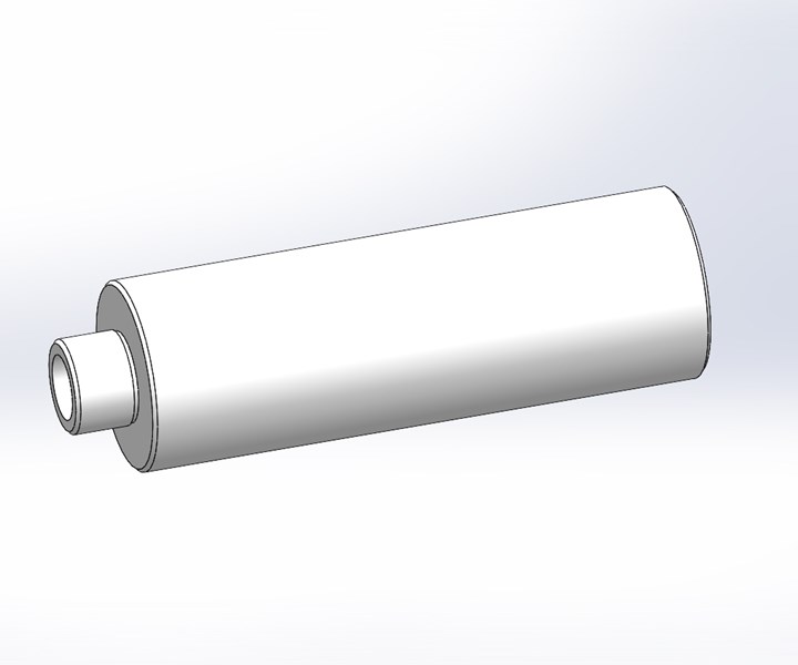
FIG 4 Support pillar/guide pin supported on one end.
The design shown in Fig. 5 is supported on both ends, and is best for larger molds with heavier plates. Whichever method you use, be sure the support pillar/guide pin is nitrided for longevity. The center of nitrided guide pins and leader pins are soft enough to machine readily—about 25 to 35 Rc.
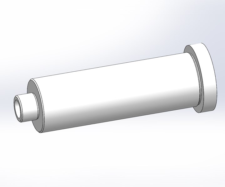
FIG 5 Support pillar/guide pin supported on both ends.
ABOUT THE AUTHOR: Jim Fattori is a third-generation molder with more than 40 years of experience in engineering and project management for custom and captive molders. He is the founder of Injection Mold Consulting LLC in Pennsylvania. Contact: jim@injectionmoldconsulting.com;
injectionmoldconsulting.com


Related Content

Fundamentals of Polyethylene – Part 6: PE Performance
Don’t assume you know everything there is to know about PE because it’s been around so long. Here is yet another example of how the performance of PE is influenced by molecular weight and density.
Read More
What to Look for in High-Speed Automation for Pipette Production
Automation is a must-have for molders of pipettes. Make sure your supplier provides assurances of throughput and output, manpower utilization, floor space consumption and payback period.
Read More
Use These 7 Parameters to Unravel the Melt Temperature Mystery
Despite its integral role in a stable process and consistent parts, true melt temperature in injection molding can be an enigma. Learning more about these seven parameters may help you solve the puzzle.
Read More
Optimizing Pack & Hold Times for Hot-Runner & Valve-Gated Molds
Using scientific procedures will help you put an end to all that time-consuming trial and error. Part 1 of 2.
Read MoreRead Next

Tooling: Why Ejector Pins Break...and How to Prevent It, Part 1
In part one of this four-part series, we focus on the molding machine and the ejection system as culprits.
Read More
Lead the Conversation, Change the Conversation
Coverage of single-use plastics can be both misleading and demoralizing. Here are 10 tips for changing the perception of the plastics industry at your company and in your community.
Read More
For PLASTICS' CEO Seaholm, NPE to Shine Light on Sustainability Successes
With advocacy, communication and sustainability as three main pillars, Seaholm leads a trade association to NPE that ‘is more active today than we have ever been.’
Read More