
The Awful Truth About Weld Lines
As everyone knows, weld lines are weak points. What’s less well known is just what’s going on inside that weld line on a microstructural level. Here’s a close-up look at some nasty little secrets.


Image used by John Bozzelli in his training seminars shows a short shot with a weld line forming around a square hole. In his experience, a microscopic air gap is apt to remain between the flow fronts even after the part is fully packed. (The training tool was designed by consultant Glenn Beall to illustrate design and molding problems.)
Who knows what evil lurks within weld lines? One who does know is molding expert, trainer and technical guru John Bozzelli, a prolific contributor to this magazine. When he worked in R&D at Dow Chemical, Bozzelli had access to an electron microscopy lab. He recalls the case of an unfilled ABS computer keycap back in 1987: The weld line where three flow fronts came together was “barely visible—barely a scratch to the human eye.” Under a transmission electron microscope (TEM), the ABS flow fronts appeared as a gray “soup,” larded with darker blobs of the rubber phase; but between the flow fronts, the scan was pure white. “Nobody could believe there was nothing between the flow fronts,” Bozzelli states. That was a revelation of the true nature of weld lines.
I’ve been thinking about weld lines lately. We published in Plastics Technology a two-part series from Avient on molding long- and short-fiber reinforced thermoplastics; Part 2 comes out in March. Both parts note that fiber-reinforced plastics lose much of their robustness at weld lines, because the fibers tend to line up side by side, rather than “reach across” the point where flow fronts meet. It’s not just a problem for reinforced plastics.


It’s widely known that when flow fronts converge at a weld line, the polymer chains (like fiber reinforcements) tend not to intermingle across the boundary. As Bozzelli puts it, “Weld lines are weak because you do not have any polymer chain bridging the weld line.” But his TEM photo (not available for publication) shows that’s not just a matter of polymer chains butting up against each other without intermingling. In some, or perhaps many, areas of the weld line, the polymer chains do not even meet!
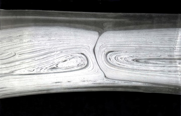
Under a microscope, air gap is visible between flow fronts of a fully packed ABS part. Striations are due to incomplete color mixing. (Photo: John Bozzelli)
How common is this, really? Bozzelli answers, “As I remember, nearly all of the TEMs that I had done at Dow showed an air gap, whether the resin was filled or unfilled, filled being a bit worse. Since I left Dow, I try to break the part at the weld line and look at the surface of the break on both sides under a simple magnifying glass. Sometimes the areas on both sides of the weld line are glossy and cupped inward, an indication of a bubble or air. Also, often they do not match or mate, so to me that is an indication that the flow fronts were separated by an air gap. Filled or unfilled, I see this about 65% of the time. Now, I just assume it is there and do what I can to eliminate or reduce the weld line. Installing vents near the area often helps, But once you put in a vent on the parting line near the weld line, the weld line often moves and then you have to put in another vent. Vacuum on the mold does help and many times eliminates the weld line.”
What else can you do about weld lines—besides redesigning the mold or gate locations or adjust the flow pattern during fill with sequential valve gating? I recently saw a report on this issue from Moldex3D, the maker of molding simulation software. It explored the use of an overflow well (see illustration) that is designed to fill after the weld line forms, such that filling the well causes melt flow across the weld line. Simulations of 35% glass-reinforced nylon 66 indicated that higher mechanical properties should result from use of the overflow well.
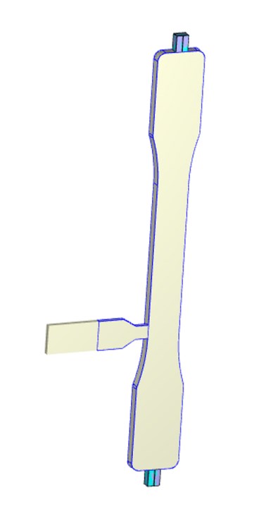 Adding an overflow well that is positioned to fill after the weld line forms can help strengthen the weld-line area by promoting flow through the weld line. Moldex3D simulated this effect on a double end-gated test bar and confirmed the effect with mechanical tests on molded parts. (Image: Moldex3D)
I asked Bozzelli what he thinks of this approach. He responds, “Adding the overflow channel to improve weld-line strength is not common, but I have seen it done a number of times. Yes, it does help, for two reasons: Often the weld line traps air and the ‘dump’ acts as a vent to allow the air to escape. That helps. Second, depending on the size of the overflow well, you get a little bit of flow melding together, and that helps strength so that you have some intertwining of the polymer chains. This is similar to putting whatever is causing the weld line, like a hole in a part, away from the end of fill. Plastic then has a chance to flow around the hole and re-meld as it continues to fill the part. That really helps to improve strength.”
If all this isn’t enough to inspire a righteous fear of the harm that weld lines can cause if placed in critical locations, Bozzelli knows of one more “evil” that lurks within those weld lines: “Take another look at the TEM photo of the ABS keycap. First is the air gap; but on one side, note the black line separating two flow fronts. That’s not supposed to be there. Yet another problem!”
Air gaps in weld lines are bad enough, but the full story is even worse.
Bozzelli explains, “It’s a huge issue in the industry that few know about. Many resin suppliers actually make thing worse by putting in too much lube, wax or flow aids. The black line of material is not ABS, but a wax, oil or other additive that phase-separated. It is much lower in molecular weight and rushes to the flow front because it is much easier flowing than the plastic and forms a barrier preventing the two flow fronts from melding together. Again, no wonder weld lines are weak—this is not a junction of plastic to plastic, but of plastic to wax. Most plastics have some additive that is low in molecular weight and has the potential to phase-separate. Make a guess how many plastics people even have a hint about this issue.”
And where would we be without the handful of uber-experienced plastics veterans who generously share their hard-earned knowledge about industry-wide problems like this?


Related Content

Improve The Cooling Performance Of Your Molds
Need to figure out your mold-cooling energy requirements for the various polymers you run? What about sizing cooling circuits so they provide adequate cooling capacity? Learn the tricks of the trade here.
Read More
How to Get Rid of Bubbles in Injection Molding
First find out if they are the result of trapped gas or a vacuum void. Then follow these steps to get rid of them.
Read More
How to Mount an Injection Mold
Five industry pros with more than 200 years of combined molding experience provide step-by-step best practices on mounting a mold in a horizontal injection molding machine.
Read More
Know Your Options in Injection Machine Nozzles
Improvements in nozzle design in recent years overcome some of the limitations of previous filter, mixing, and shut-off nozzles.
Read MoreRead Next

The Long and Short of It (Part 1)—Tips for Molding Long Fiber-Reinforced Polymers
In Part 1 of this series, we address long-fiber processing fundamentals and best practices, including practical tips and guidance on maintaining fiber length and deriving maximum advantages for demanding end applications. Part 2 will provide the same information for short-fiber materials.
Read More
The Difference Between Knit and Meld Lines--and Why It Matters
In many part designs, flow fronts will inevitably be split, but how and where they come back together is hugely important to the molded part’s finished strength.
Read More
The Long and Short of It (Part 2)—Tips for Molding Short-Fiber Reinforced Polymers
Following on a similar guide for long-fiber reinforced compounds, here are practical tips on designing and injection molding parts utilizing short-fiber reinforcements.
Read More