
How Many Parts Will My Mold Make? Part 1
Follow these guidelines to extend the life of a mold and reduce repair costs.


I have a 1982 edition of the Classifications of Injection Molds for Thermoplastic Materials by the Society of the Plastics Industry (now the Plastics Industry Association, or PLASTICS). My edition defines the construction requirements for various types of molds for machines up to 400 tons and labels them type 101 through 105. It also has three types of quick-change mold inserts, which are labeled type I through III. It specifies similar classifications for molds that require machines with 400 tons or more of clamp pressure. Each type has a specific number of cycles a mold is capable of producing. Table 1 summarizes these classifications and lifespan quantities.
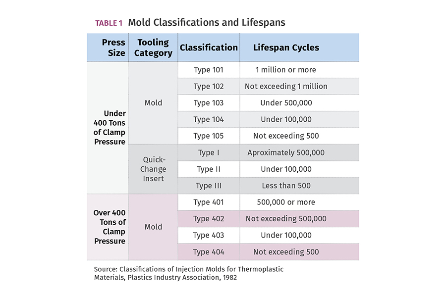
Table 1
Supposedly, the classifications were updated back in 1996. More recently, there was an article in the August 19, 2021, edition of Plastics News mentioning that these standards are once again in the process of being updated by a team of industry leaders, association members and select members of the American Mold Builders Association. We should applaud their efforts to further improve this important document.


Every customer I’ve ever had always asked how many parts their mold could make. Most moldmakers will respond to that question by saying something like, “Well, you paid for a Class 101 mold, so it should produce up to 1 million cycles.” Obviously, that answer is based on the PLASTICS mold classifications. While the classifications and the requirements for those classifications are excellent, I don’t agree with specifying the number of cycles each type of mold should be able to produce.
The PLASTICS document is meant to be a guideline for purchasers of injection molds, and it should be renamed accordingly—guideline. The problem is that many people consider the stated minimum cycle counts to be factual, if not contractual. And that can lead to problems down the road. What happens to a class 101 mold at a million and one cycles? The customer pays for all the maintenance and repairs to the mold—regardless of how small or how large the cost? What happens at 999,000 cycles if a cavity cracks? Does the moldmaker have to replace it at his cost? As unpleasant as this topic is, it may be worth setting some initial ground rules with your customers.
Never guarantee the longevity of a mold.
There are many factors that determine the longevity of a mold. Part complexity, which dictates mold complexity, is probably the biggest factor. A mold that produces a flowerpot, 5-gal bucket or a Frisbee can last a very long time. But more complex molds, such as those with cam action, unscrewing mechanisms, collapsible cores, contoured parting lines, sliding shutoffs, etc., will not last nearly as long because there are more component parts that can wear, break, gall, or seize. Just because a mold is made of heat-treated tool steel doesn’t mean it’s going to pump out hundreds of thousands of parts.
For example, if a part design has sharp outside corners (meaning sharp inside corners in the mold) and is subjected to high injection pressures, it’s longevity could be very short due to the potential of fracturing. I’ve seen well-built, class 101 hot-runner molds fail after the first five minutes because the manifold filled up with plastic—snapping bolts and splitting plates apart. I have also seen dead-soft aluminum molds run trouble-free for well over a decade.

FIG 1 Hobbed copper cavity inserts. (Photos: J. Fattori)
Figure 1 shows a cavity set for a toy soldier. It was made in 1955 by hobbing blocks of copper. Hobbing is a manufacturing method rarely used today. Non-alloyed copper is also rarely used today because it is extremely soft. The figurine in Fig. 2 (left) was originally molded out of PS. The figurine in Fig. 2 (right) was cast out of liquid silicone material a few weeks ago on my desk. There’s a little flash on the cast part, but the “clamp pressure” was only about 10 lb—generated by a few rubber bands. The point is that part geometry is where it all begins, and oftentimes, defines when it all ends.
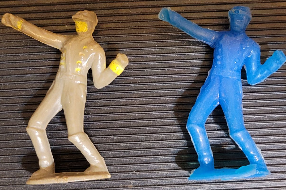
FIG 2 Molded figurines.
Just like an airplane, car, boat or motorcycle, a mold can potentially last forever if it is maintained properly and repaired when necessary. The only time a mold is considered unusable or has reached the end of its lifespan is when the repair cost exceeds its worth. In addition to the part and mold complexity, the mold’s longevity is based on many other factors, including (but not limited to) the mold design, steel selection, quality of the mold components and construction, the molding machine it runs in, molding material type and molding process used to make the parts, as well as the mold installation, removal, maintenance and storage.
The only time a mold is considered unusable or has reached the end of its lifespan is when the repair cost exceeds its worth.
A moldmaker’s objective is to maximize the performance of a mold to achieve the lowest possible total cost per part based on the intended lifespan of the project. That analysis should include the goal of minimizing the cost to maintain the mold. Therefore, when reviewing a new project, moldmakers will wisely ask:
1. What is the expected annual quantity? This helps the moldmaker decide the mold classification and the number of cavities required to meet those annual quantities.
2. What is the part used for? If it’s a medical, optical or automotive part, there’s a very good chance that the mold is required to be made of ESR (electroslag reduction) stainless steel for cleanroom conditions and optical polishing or mold texturing.
3. What is the molding material? If it’s a corrosive resin, such as rigid PVC, the only good option is to make the mold out of stainless steel. I say the only good option because nickel and other coatings do not protect carbon steels from PVC gases for very long. If you think that stainless is too expensive, consider the cost to remove the worn or flaking plating, re-polishing the cores and cavities and then re-plating the mold.
If the material is highly abrasive, such as those with glass fillers, all the surfaces in contact with the plastic need to be through-hardened—the harder the better. That includes the sprue bushing and runner inserts, not just the cavities and cores. Abrasive materials can also dictate that the gate(s) be inserted because they will be the first thing(s) to wear out. Steels with high concentrations of carbon and chrome typically have good wear resistance. If the material is extremely abrasive, such as a thermally conductive material with silicon carbide filler, then one of the powdered-metal tool steels with a typical hardness value of about 60 Rockwell C could be best suited.
4. Is there a dimensioned 2D drawing of the part? I have seen too many jobs quoted strictly based on a 3D CAD model. CAD models do not specify the tolerances for critical dimensions. Nor do they specify the surface finish, aesthetic areas that cannot have gate or ejector-pin marks, secondary operations, mating parts, etc. 2D drawings almost always help the moldmaker decide the best way to design and build a mold—or if the part is even moldable to the stated specifications.
5. Is there a target price for the molded part? This is a common question for thin-walled and commodity parts, such as caps and closures, where cycle time is critical and the need for a hot-runner system is paramount. High-thermal-conductivity materials such as copper alloys may be required. Unfortunately, too few moldmakers ask this question—unless they are also going to be the molder.
Personally, I have a passion for using thermally conductive materials, especially in hard-to-cool areas. Not because they are great at reducing cycle time, but because they are great at achieving uniform cooling. Non-uniform part cooling invites part warpage, and warped parts are often a rejectable condition. Table 2 gives approximate thermal-conductivity values for various mold materials. These values can vary widely depending on the manufacturer, heat treatment and operating temperature.
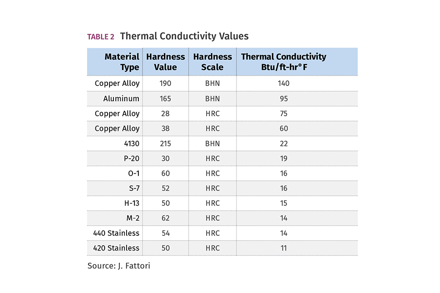
Table 2
The thickness of the molded part is important when it comes to selecting the best material out of which to make the cavities and cores. If the part is thin-walled, selecting a material with extremely high thermal conductivity may not be the best choice. The material can solidify too quickly during injection, and you can end up with a lot of short shots or injection pressures that exceed the machine’s capabilities. Conversely, if the part is extremely thick, the thermal conductivity of the cavity and core material is not nearly as important because the molded part forms an exterior skin, which acts as an insulating barrier. That’s why a graph of cooling time vs. wall thickness is not a straight line. It is an upwardly projecting curve.
Proper steel selection plays a critical role in the longevity of a mold. Most moldmakers have their “go-to” types, such as 1030 or 4130 for the mold base and P-20, 420 or H-13 for the cavities and cores. 1030 and 4130 are good steel types for mold bases, but if the project needs to last for several years, or if the water quality in the molding facility is prone to calcium deposits, the mold base should be electroless nickel plated.
A pre-hardened stainless-steel mold base is an even better solution. The thermal conductivity of stainless isn’t as good, but it usually doesn’t matter for a mold base. I always wondered about moldmakers who prefer steel types that have good weldability. While that is a good property to have, it shouldn’t be a guiding factor. Some steel preferences are based on years of experience. Some are based on how easy they are to machine, or how much they change size or warp during heat treatment. Usually, the commonly used steels are more than adequate for most parts. But occasionally the properties of the steel should be given greater consideration.
I have already mentioned polishability, thermal conductivity, hardness and corrosion resistance. But what about toughness, compressive strength, wear and abrasion resistance? These are important properties to consider as well, especially when two pieces of steel slide against each other, like a cam, lifter or shutoff. The old rule of thumb says that if different steel types are used and there is a 10-point Rockwell C differential between them, everything will be fine. That rule of thumb doesn’t always hold true—especially if the forces are high and the contact area is large. O-6 and A-10 steels are good for sliding applications because these two steels have high concentrations of graphitic particles in their microstructure. O-1, O-2, D-2 and S-1 are also good steel types for sliding applications.
A very common cause of mold damage is due to galling. When two pieces of steel rub or slide against each other, there is a risk of them metallurgically bonding together. You can usually hear the components squeaking shortly before they seize up. Galling can occur at any time—from the initial mold sampling up to 1 million cycles later. Everyone from the machine operator to the plant manager should be aware of what this sound means. Recognizing a galling situation early can reduce the amount of mold damage.
Wear and galling explain why there has been a lot of attention given to various surface coatings and surface treatments, as well as the metallurgical compatibility of different types of mating steels.
Toughness, which is basically a combination of strength and ductility, is important for tall, free-standing cores, as well as cavities with sharp inside corners where cracking from molding pressures is a concern. H-13 has very good toughness properties. S-7 is also good.
Some of the common causes for a mold’s decreased longevity are due to accidents on the production floor. The folks in the trenches describe such events as “crashes.” One of the most common crashes involves a cam that is out of position—usually after cleaning the parting line or removing a part, or simply because the cam retention device was too weak, and the cam slid out of position. When a cam is out of position, the angle pin does not line up with the hole in the cam and then—crash—it snaps like a twig. If the angle pin hits the top of the cam, it’s usually not a big deal. Simply replace the pin. But if it hits any cavity impression, that’s going to end the production run and cost a lot more to repair. Another common type of crash is handling a mold with one eyebolt and no safety strap. An unsecured mold half can easily hit the ground well before you can yell “Look out!”
Galling can occur at any time—from the initial mold sampling up to 1 million cycles later.
An uncommon, but very serious crash can occur when a large mold is hung in the machine in two halves. If one of the halves is accidentally oriented 180° out of position and the setup man overrides the low-pressure setup mode because the mold won’t close, really bad things happen. On a couple of occasions, I have seen a molding machine with a bad hydraulic valve. The mold closed at full velocity and shook the entire building. But accidental mold crashes are thankfully infrequent and one-time events.
The real mold killer—for any mold, of any complexity—is parting-line flash. When plastic or other debris adheres to the parting line of a mold, it can deform the mold by leaving an impression or indentation. If you think about it, when debris is sandwiched between two flat surfaces and is exposed to a few hundred tons of clamp pressure, it has nowhere to go but in.
Let’s do some simple math. Assume a sub-gated part leaves 1/16-in. diam. flakes on the parting line. A 1/16-in. diam. flake has an area of 0.0031 in.2. The mold is in a 500-ton press. Pressure = Force ÷ Area so in this case:
500 tons ÷ 0.0031 in.2 = roughly 160,000 psi.
The yield strength of P-20 steel is about 125,000 psi. The yield strength of 1030 and 4130 steel is about 64,000 psi. This equation doesn’t even include the added force applied to the debris due to the closing speed and momentum of the moving platen. Figure 3 shows what gate flakes can do to a mold when the applied pressure is considerably greater than the yield strength of the steel.
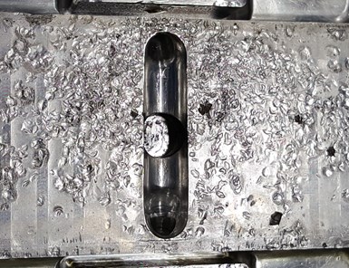
FIG 3 Sub-gate flake damage.
If the injection or packing pressure is excessive, or if the clamp pressure is insufficient, the plastic will try to ooze out of the cavity. This usually results in the sharp-edged perimeter of the cavity starting to look like someone added a small radius to it. Over time, the cavity will have more and more flash growing around it. The problem with flash is that once the surface of a mold is indented, it never gets better. It can only get worse. It needs to be repaired and the root cause determined and corrected when it’s first noticed. Giving an operator a razor blade or some other tool to remove the flash is not an appropriate corrective action.
Flash never gets better. It only gets worse.
While it’s true that heat-treated tool steels with high compressive strength can delay the amount or severity of flash damage, it cannot make the mold impervious to damage. Figure 4 shows a severely hobbed parting line of a pre-hardened 28-32 Rockwell C mold caused by nozzle strings. Generally speaking, the harder the tool steel is, the more brittle it is. Obviously, there is a tradeoff when it comes to the physical properties of metals. Depending on several factors, you might need to consider using a more ductile material, or making a spare cavity set as insurance.
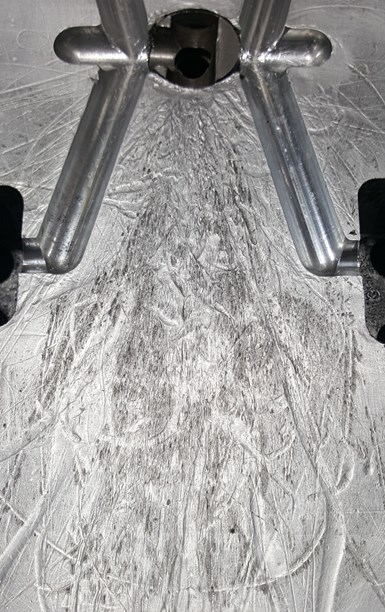
FIG 4 A hobbed parting line.
The hardness of the plastic, as well as the hardness of the mold can dictate how quickly and how severely the mold will get damaged. If a hot bushing is drooling Ultem PEI in a P-20 mold, it won’t be long before you are grinding a few thousandths off the parting line to clean it up. I know moldmakers that intentionally make the mold cores 0.005 in. taller because they believe they will be grinding the parting line a couple of times over the life of the mold. But the hardnesses of the plastic and the steel are not the only factors that promote flash. The list of potential causes is exhaustingly long. Here are some of the more common ones:
• Inferior mold design
• Inferior mold construction
• Insufficient mold-plate thicknesses
• Insufficient support-pillar area
• Lack of parting-line relief
• Improper mold setup
• Insufficient clamp pressure
• Excessive clamp pressure
• Cavity imbalance
• Poor processing parameters
• Excessive injection or pack pressures
• Low material viscosity
• Insufficient venting
• Excessive vent depth
• Using adhesive labels as vents
• Machine bushing wear
• Machine platen wear
• Lack of alignment
• Worn shutoffs
• Abrasive molding material
• Abrasive material fillers
• Nozzle stringing
• Sub-gate flaking
• Sticking parts or runners
• Rust or corrosion
• Lack of preventive maintenance
Several of these factors were discussed in this article. Future articles will discuss the remaining issues.
Acknowledgement: I want to thank Brenda Clark of Hasco America; Patricia Miller of Uddeholm; Roy Glenn, retired mold builder and designer; and Rick DeBeer, retired from LyondellBasell, for their knowledge and insight, which helped me compose this article.
ABOUT THE AUTHOR: Jim Fattori is a third-generation molder with more than 40 years of experience in engineering and project management for custom and captive molders. He is the founder of Injection Mold Consulting LLC in Pennsylvania. Contact: jim@injectionmoldconsulting.com;
injectionmoldconsulting.com


Related Content

Optimizing Pack & Hold Times for Hot-Runner & Valve-Gated Molds
Using scientific procedures will help you put an end to all that time-consuming trial and error. Part 1 of 2.
Read More
Why Shoulder Bolts Are Too Important to Ignore (Part 2)
Follow these tips and tricks for a better design.
Read More
How to Optimize Pack & Hold Times for Hot-Runner & Valve-Gated Molds
Applying a scientific method to what is typically a trial-and-error process. Part 2 of 2.
Read More
Back to Basics on Mold Venting (Part 2: Shape, Dimensions, Details)
Here’s how to get the most out of your stationary mold vents.
Read MoreRead Next

Processor Turns to AI to Help Keep Machines Humming
At captive processor McConkey, a new generation of artificial intelligence models, highlighted by ChatGPT, is helping it wade through the shortage of skilled labor and keep its production lines churning out good parts.
Read More
Advanced Recycling: Beyond Pyrolysis
Consumer-product brand owners increasingly see advanced chemical recycling as a necessary complement to mechanical recycling if they are to meet ambitious goals for a circular economy in the next decade. Dozens of technology providers are developing new technologies to overcome the limitations of existing pyrolysis methods and to commercialize various alternative approaches to chemical recycling of plastics.
Read More