Tooling: Why Ejector Pins Break...and How to Prevent It, Part 1
In part one of this four-part series, we focus on the molding machine and the ejection system as culprits.

If the molding machine’s ejector cross is bent, it will apply an uneven load on the mold’s ejector system.
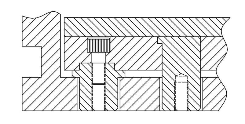
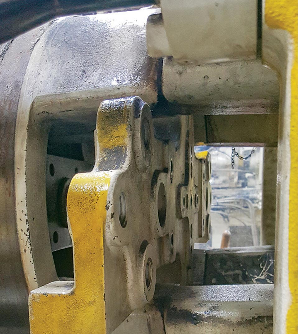
Ejector extension designs should apply the machine’s ejection force to the thicker ejector plate (left) and not the weaker retainer plate (right).
A single offset cavity puts an uneven load on the ejection system.
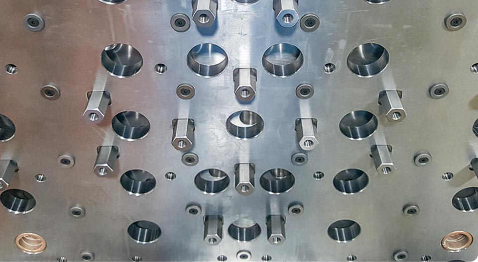
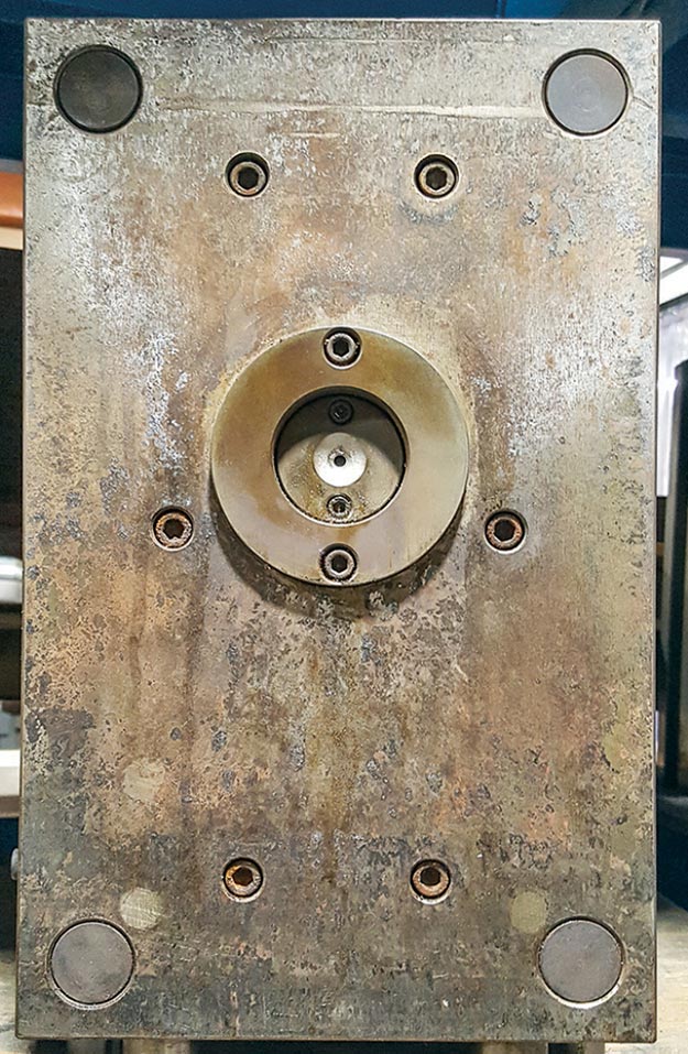
Always equip a mold with all of the possible machine knockout patterns, and be generous with the rest buttons.


There are dozens of reasons why ejector pins break. Very few of them have anything to do with the pins themselves. This month I will discuss how the molding machine and the ejection system can be the culprit.
If the molding machine has a bent ejector cross (also known as the machine’s ejector platen, ejector plate, or if you’re old school like me, the dog bone), or if the cross’s thin guide bushings are worn, it will travel at a slight angle and apply an uneven load to the mold’s ejector plate.


This condition is usually obvious because the machine’s knock-out bars may not align with, or will rub against, some of the through holes in the moving platen. Steel crosses that are bent can be straightened out in a hydraulic press, but cast-iron crosses will probably crack.
If you have an ejector-plate deflection issue, the root cause of the problem is probably not the thickness of the plate.
A more common condition that will apply an uneven load to the ejector plate is if the molding machine’s knock-out bars are slightly different lengths. Bars that are too long or of different lengths are the primary reason for bent ejector crosses. If the mold has knock-out extensions attached to the ejector plate, and they are not the same length, or one of their retaining bolts comes loose, this too can cause an uneven load on the ejector plate. Several mold-components suppliers sell standardized knock-out extensions. If you have your own design, make sure the extensions do not butt up against the back of the ejector retainer plate. Those designs are notorious for bending or breaking the retainer plate.
If the mold is equipped with a coil-spring ejector-return system, but one or more of the springs are broken, the ejector plates are going to try to twist or bend. This will also happen if the springs are of different lengths, or if the amount of preload varies due to varying counter-bore depths. I try to avoid using ejector-return springs. I once had a spring-loaded ejection system bind in the forward position. The foreman gave the ejector plate a hard tap with a brass rod. It broke free and slammed back against the support buttons—thankfully not against his fingers. Someone once told me he loves springs. “It speeds up the setup time because we don’t have to connect the machine’s ejector bars.” I’m guessing he doesn't connect his seat belt either.
Another thing that can cause an uneven load on the ejector plate is the location of the ejector pins and of the forces required to eject the part. This is always the case when there is a single offset cavity.
When there is an uneven load applied to the ejector plate, it will try to bend, cock, or twist. This causes a chain reaction. If the ejector plates have a guided system, the guide bushings will wear out prematurely.
It can cause ejector pins to bend and break. It can cause the through holes in the core insert to wear out with elliptical or egg-shaped holes. It can cause the ejector pins to push against the molded part unevenly, which can distort the part or cause it to stick in the mold tighter. And it can cause the ejector pins to vary in height relative to the parting line.
Did you ever wonder why molds have those round stop pins or rest buttons between the ejector plate and the clamp plate? They are there because if any dirt or debris gets in between these two plates, some or all the ejector pins are going to protrude beyond the parting line of the mold by an amount equal to the thickness of the debris. Protruding pins can cause sticking issues when trying to eject the part. If any ejector pins are under a cam, the pin or the cam can get damaged when the mold closes. The purpose of these rest buttons is to minimize the contact area between the two plates, to allow some debris to accumulate without affecting the proper position of the ejector system.
On occasion, rest buttons are moved or eliminated to make room for a core pin or some other component. This is when you can get a support problem. It is a good idea to have a rest button near or under any component that could apply pressure to the ejector plate, such as a lifter or an ejector pin that butts up against steel. Having rest buttons near the tapped holes for the machine’s ejector bars is also beneficial. If the machine’s retract position is not set properly, ejector bars can pull and distort a poorly supported ejector plate.
Ejector housings are typically open on two opposing ends of a mold, and one of the open ends is often at the top when mounted in the machine. It is not that uncommon for small molded parts with undercuts on their cores to ricochet off the cavity upon ejection and end up inside the ejector housing. That can cause the ejector plates to try to bend the next time the mold cycles. This is easily correctable by installing an ejector housing cover or shield. Housing covers have additional benefits, as well.
They are a good safety precaution for accidents caused by spring-loaded ejector plates—much more effective than painting the edges of the plates OSHA orange. A cover also helps prevent potential mold damage by personnel trying to advance the ejector plates with a pry bar when there is an ejector pin under a cam. In lieu of a shield, rest buttons, which are typically mounted between the clamp plate and the ejector plate, can be added between the retainer plate and support plate. This creates a 3/16-in. gap, so any dirt, debris or the occasional small stray part won’t cause the ejector plates to try to cock or bend. I only suggest this because most processors set the ejection forward position to be flush with the back of the support plate, even when they have plenty of ejector stroke, as opposed to staying a short distance away.
Always install all the Plastics Industry Association’s (PLASTICS) knockout patterns that will fit in a mold. If you don’t know what they are, get a copy of AN-109 Recommended Guidelines–Interchangeable Mold Mounting Dimensions from PLASTICS. It is up to the setup man to decide which ejector pattern(s) to use. Hopefully, he chooses a pattern that will not damage the mold. Hydraulic ejector cylinders on small molding machines can have a forward ejection force of 1 to 5 tons. Larger machines can go as high as 80 tons. Now that’s a force to be reckoned with! On large molds, if the knock-out bars are not spaced far enough apart, this can cause the plates to want to bend in the middle—toward the support plate.
Conversely, if the knock-out bars are at the extreme outer edges, but there are a number of ejector pins pushing the runner and parts in the middle of the mold, the ejector plates will also want to bend in the middle—but this time away from the support plate. Therefore, make sure the knock-out bars are evenly spaced; or on large molds, consider using additional knock-out bars to help distribute the force evenly over the entire ejector plate.
Installing additional bolts connecting the ejector retainer plate to the ejector plate will provide some added strength to prevent the two plates from trying to bend or twist. But they do a much better job of preventing just the ejector retainer plate from bending, which is important. Extra bolts placed near the return pins, lifters and any groupings of ejector pins help prevent the weak retainer plate from separating from the ejector plate as the assembly retracts.
The formula for calculating the amount of deflection a rectangular plate will have under a specific set of conditions states that the plate’s resistance to deflection is proportional to the third power of its thickness. In that same formula, the unsupported length is also proportional to the third power. This is why it is so important for the machine’s ejector bars to be evenly spaced.
This deflection formula is important when molding a part with a large amount of projected area or calculating how thick to make a support plate or a cavity plate in a hot-runner mold. But when it comes to an ejector plate, the standard 1-in. or 1 1/8-in. thickness is almost always sufficient. If you have a plate-deflection issue, the root cause of your problem is probably not the thickness of the plate; more likely it’s an uneven loading issue.
However, I do recall a large mold or two where we used a 1 3/8-in.-thick ejector plate, but only because it was riddled with holes from support pillars and numerous other mold components.
Ejector plates should travel parallel to the centerline of the mold, and receive and apply an evenly distributed load.
Once I went so far as to heat treat an ejector plate made of S-7 steel and guided it with linear ball bearings for an electrical connector molded in liquid-crystal polymer. The reason wasn’t possible plate deflection. The concern was that the ejector-pin height tolerance on the drawing was +0.0000 to -0.0005 in. If the head of the pin made even a slight depression into the face of a softer ejector plate, or if the ejector plate was even slightly out of alignment, the parts would be rejected.
While it is a little beyond the scope of this article, I should point out that it is good practice for ejector pins to be 0.0005 in. to 0.0015 in. below the surface of the part they are ejecting. This helps ensure the part will not hang up on the pin, which would require additional ejector pulses. It also helps reduce stress marks and “skid” marks on the part itself. Conversely, if the ejector pins are slightly into the part, you can get aesthetic issues caused by turbulent material flow, particularly on thin-walled parts. You may have seen this happen on a molded part with depressed engraving, formed by raised engraving in the steel.
Thermal expansion is a major cause of ejector-pin misalignment, especially on large molds that run at elevated temperatures. Just because the ejector plates move freely back and forth on the bench doesn't mean they won’t bind up under production conditions. The core and the support plate are rarely at ambient temperature. Ejector plates are almost always at ambient temperature. If the core plate expands (or contracts) and the ejector plates don’t, some of the ejector pins will be out of alignment—typically the outboard ones. It all comes down to what the temperature delta is, and what is the distance between the outboard ejector pins.
This thermal-expansion problem can easily be solved by doing two things: First, add cooling lines (water or oil), in the ejector plate. Second, if the ejector plates are guided, mount the guide pins in the support plate—not the ejection clamp plate. My personal preference is to mount the guide pins in the support plate in every mold.
If you ever wonder whether you should add a guided ejector system, ask yourself if the plates are heavy, or is the annual number of cycles 100,000 or more. If you answer yes to either question, the ejector system should definitely be guided. Otherwise, you can expect to eventually get premature ejector-pin wear and its associated down-flash sometime during the mold’s lifespan. Even if the answer is no, it’s still a good idea to help avoid wear and pin breakage problems. PLASTICS has a publication entitled Classification of Injection Molds for Thermoplastic Materials. It specifies that Type 101 and 401 molds must have guided ejection, and this is recommended for Type 102 and 402 molds as well. As a point of interest, Mike Noggle and Chuck Brewer Jr., along with Jack Kelly and Jim Atchison, hammered out the details of these mold classifications and assigned their work to the trade association in 1978.
Very large molds should have six or eight ejector-return pins—not the typical four. Additional return pins help ensure the ejector plates are pushed back evenly. And if the ejector plates are not tied into the machine’s ejector cross, the added return pins will reduce the amount of coining on the face of the cavity plate.
This also happens on small molds made of pre-hard or softer steels. Some quick-change mold inserts are supplied with only two return pins and they are considerably smaller than what is required for a long-running mold.
Bottom line: To help avoid ejector-pin failure, the ejector plates should travel parallel to the centerline of the mold, and the plates should receive and apply an evenly distributed load.
ABOUT THE AUTHOR: Jim Fattori is a third-generation injection molder with more than 40 years of molding experience. He is the founder of Injection Mold Consulting LLC, and is also a project engineer for a large, multi-plant molder in New Jersey. Contact jim@injectionmoldconsulting.com; injectionmoldconsulting.com.
Related Content

Back to Basics on Mold Venting (Part 1)
Here’s what you need to know to improve the quality of your parts and to protect your molds.
Read More
Why Shoulder Bolts Are Too Important to Ignore (Part 1)
These humble but essential fasteners used in injection molds are known by various names and used for a number of purposes.
Read More
Improve The Cooling Performance Of Your Molds
Need to figure out your mold-cooling energy requirements for the various polymers you run? What about sizing cooling circuits so they provide adequate cooling capacity? Learn the tricks of the trade here.
Read More
Where and How to Vent Injection Molds: Part 3
Questioning several “rules of thumb” about venting injection molds.
Read MoreRead Next

People 4.0 – How to Get Buy-In from Your Staff for Industry 4.0 Systems
Implementing a production monitoring system as the foundation of a ‘smart factory’ is about integrating people with new technology as much as it is about integrating machines and computers. Here are tips from a company that has gone through the process.
Read More
Understanding Melting in Single-Screw Extruders
You can better visualize the melting process by “flipping” the observation point so that the barrel appears to be turning clockwise around a stationary screw.
Read More
Troubleshooting Screw and Barrel Wear in Extrusion
Extruder screws and barrels will wear over time. If you are seeing a reduction in specific rate and higher discharge temperatures, wear is the likely culprit.
Read More