


Corotating, intermeshing twin-screw extruders mix polymers with fillers, additives and modifiers to impart desired performance properties. Twin-screw extruders (TSEs) are available for research and development purposes to process as little as a 50-g batch, and for full-scale production at rates of more than 50,000 kg/hr. The attributes inherent in continuous compounding with twin-screw extruders make these devices unmatched for both commodity and high-tech precision products.
Twin screw extruders utilize unique screw-to-screw flows that are effective, rapid, efficient, and capable of achieving both dispersive and distributive mixing. TSEs are the most commonly used continuous-mixing device for innumerable plastics compounds with myriad characteristics. Some require dispersive mixing, and some only distributive mixing.


Rotating twin screws impart shear and energy from the motor to the process. In the TSE process section (barrels and screws), the materials are exposed to a series of unit operations—feeding, melting, mixing, venting and pumping—which together constitute the “process experience.” The segmented nature of the TSE screws, in combination with controlled pumping and wiping characteristics of self-wiping, corotating, intermeshing screws, allow the user to sequentially match screw and barrel geometries to the intended process tasks.
TSEs are complex machines that allow a wide variety of operating conditions. Control parameters include screw speed (up to 1000+ rpm), feed rate, process temperatures and vacuum level. Melt temperature, melt pressure, and motor load are monitored and controlled to ensure consistent quality of the product. Controls include PLCs and HMI screens with data acquisition, trending and recipe management.
The Mixing Experience
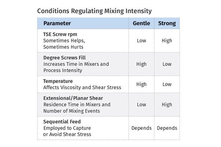
Focusing on output rate/rpm, screw design and elements, and viscosity management allows you to troubleshoot the twin-screw process to achieve a high-quality, homogenous melt without degradation.
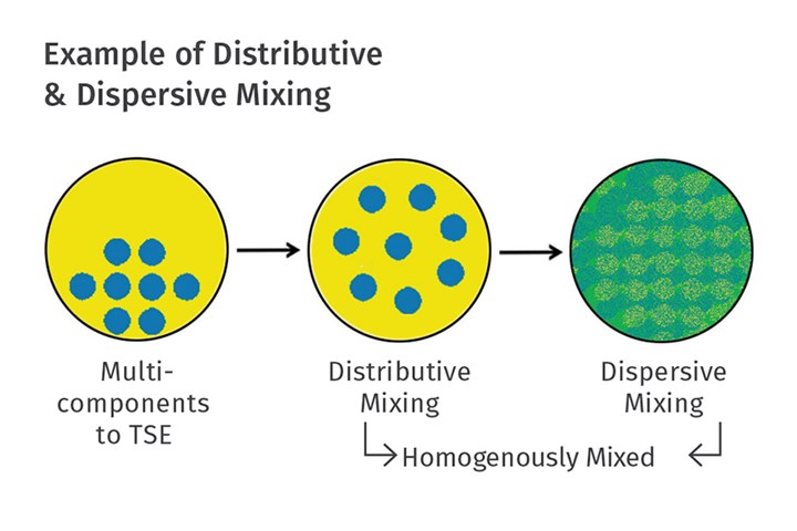
FIG 1 Conceptual representation of the “mixing experience” in twin-screw corotating extruders.
TSEs provide the unique flows needed to achieve dispersive and distributive mixing rapidly and efficiently. Dispersive mixing is when large particles are reduced (rocks transformed into sand) and distributive mixing is where components are spatially distributed without being attrited (i.e., mixing glass micro-spheres without breaking them). Dispersive mixing efficiencies rely on the strong forces applied by the viscous polymer matrix on aggregated additives, associated with the extensional and planar flow fields induced/applied almost relentlessly by mixing elements. Distributive mixing relies on repeated rearrangement of the minor-component additives (liquid or solid) while avoiding shear flows that create high-energy-consuming shear stresses.
TSEs provide the unique flows needed to achieve dispersive and distributive mixing rapidly and efficiently.
Many formulations require either or both mixing mechanisms. The goal is to achieve a homogenous mix with minimal degradation (by minimizing energy-consuming flows through judicious choice of screw elements), which is sometimes easier said than done.
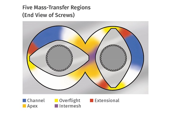
FIG 2 TSEs have four high-transfer regions and one low-transfer region (channel) for mixing.
A virtually infinite number of screw elements are available. There are, however, only three basic types of elements: flighted, mixing, and zoning. Flighted elements forward material past barrel ports, over mixers and to pump out of the TSE. Zoning elements isolate two operations within the extruder—for example, to induce a melt seal prior to a vacuum vent. Based on the staging of screw elements on high-torque splined shafts, the screw design can be made shear-intensive or passive based on the formulation requirements.
The “kneader” is the most common type of TSE mixing element. The wider the kneading element, the more dispersive it is, since extensional mixing and planar shear effects are accentuated as the materials in the channel are forced up and over the land. Narrow kneading elements, by comparison, result in distributive mixing by facilitating efficient melt-division-rate mixing with minimal dispersive influences, which helps to mix heat/shear-sensitive materials with minimal degradation/attrition. Kneading elements can be arranged with a forward pitch (less aggressive), neutral, or reverse pitch (most aggressive). High liquid-phase mixing often benefits from specialty high-division-rate distributive elements that prevent “pooling” of the liquids in the screws.
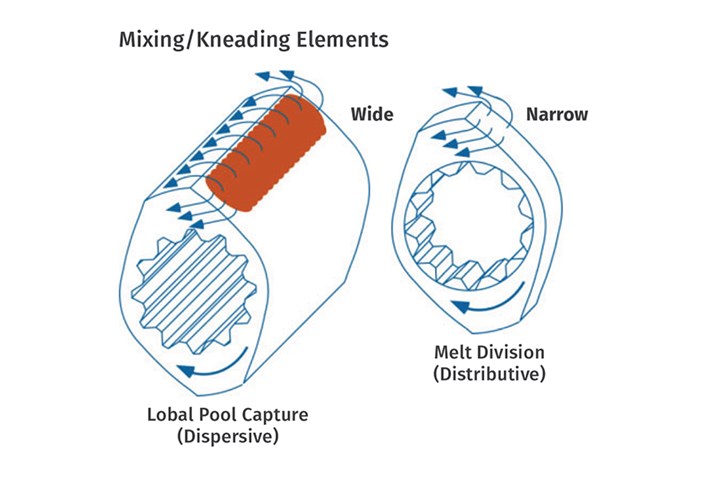
FIG 3 Wider kneading disks achieve dispersive mixing, whereas narrower disks are for distributive mixing.
Screw design can be made shear-intensive or passive based on the formulation requirements and sensitivity.
The shear rate in the gap between the tip of a kneader and barrel wall, or overflight region, is often called the peak shear rate and serves as a useful benchmark to troubleshoot mixing (and also to anticipate degradation). Peak shear rate is calculated as follows:
Peak shear rate = (π × D × n) ÷ (h × 60), where
D = Screw diameter
n = Screw rpm
h = Overflight gap.
So, for a TSE with 77.5-mm OD screw and 0.55-mm overflight kneader gap at 600 rpm, the calculation is:
(3.14 × 77.5 × 600) ÷ (0.55 × 60) = 4424.5 sec-1
This peak shear-rate calculation is admittedly an oversimplification of the “mixing experience” in a TSE, as it ignores extensional-flow mixing and apex and intermesh effects, which may be comparatively more pronounced. Regardless, the peak shear rate is easy to calculate, making it an extremely useful day-to-day tool and benchmark.
Another useful formula that should be tracked for existing compounding operations is specific energy (SE), which is the amount of power that is being input by the motor into each kg being processed. SE is a benchmark that confirms that the process and mixing are the same from batch to batch and is calculated in two steps:
Applied power: KW (applied) = KW (motor rating) × % torque × rpm running/max. rpm × 0.97 (gearbox efficiency)
Specific Energy = KW (applied) ÷ kg/hr
A lower SE indicates that less mechanical energy is being used per kg processed, and a larger SE indicates more energy use. It is important that SE records be maintained, particularly for troubleshooting. For instance, if a product always runs with an SE of around 0.25 and suddenly changes to 0.20 or 0.35 something has changed (hardware, process conditions or material) and the mix quality has to be examined, as it may be also different.
The Role of the Metering System
A premix can be metered into a TSE by a volumetric feeder. Loss-in-weight (LIW) feed streams are generally specified to accurately meter multiple feed streams into the TSE process section. The pressure gradient in the TSE process section is determined by the selection of screws and is zero at various stages in the process section, which enables the downstream introduction of materials (i.e. fillers or fibers) via side stuffers or crammers. Injection pumps are used for liquids.
Materials in different forms such as pellets, granules, powders, fibers and liquids are metered into the TSE. These extruders are starve-fed, resulting in a mostly partially filled process space between the screws and the barrel. The output rate is set by the feeder(s), and screw rpm is independent and used in concert with the rate to optimize compounding efficiencies. To a significant degree, the residence time (RT) in a TSE is based on the feed rate. The residence-time distribution (RTD) is then determined by the screw rpm. The RTD inherent with a TSE compounding system helps to “even out” minor feeder fluctuations.
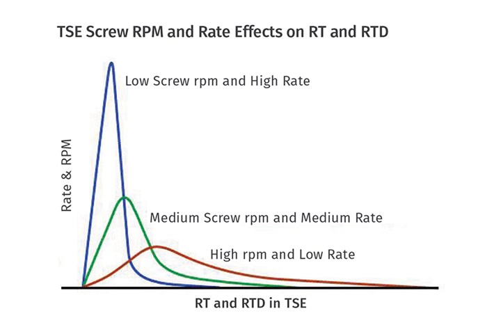
FIG 4 Rate and screw rpm work in concert to determine residence time and residence-time distribution in corotating TSEs.
Feed rate vs. screw rpm, in combination with the screw design, regulates the mass-transfer/mixing properties of the process. Since feed rate and screw rpm are inextricably linked to mixing, it is insightful to understand the five screw regions inherent in any TSE:
1. Channel: The mixing rate in the channel is similar to that of a single-screw extruder, and lower than in the other TSE shear regions
2. Overflight gap: Between the screw tip and the barrel wall, the material in this region undergoes significant planar shear effects, and it’s easy to calculate.
3. Extensional mixing zone: An extremely effective mixing mechanism occurs here as the material transitions from the channel to the overflight gap with a stretching/spatial acceleration effect. (There’s no simple formula; it requires computer modeling to calculate).
4. Apex (upper/lower): Upper and lower apex regions are where the material “feels” the second screw and where compression/expansion and directional flow fields impact mixing.
5. Intermesh: A small, finite amount of material passes between the screws and experiences an intensive shear effect. As throughputs are decreased or increased (at a constant screw rpm) the materials spend more or less time in mixing zones and thus the “mixing experience” is impacted. The RT can be less than 10 sec or as long as 10 min. Typical RTs are in the range of 20 sec to 2 min, with longer RTs being possible (and needed) for reactive processes.
As the screw rpm are decreased or increased (at a constant rate) there is a pronounced effect on the RTD and, again, the “mixing experience.” Increasing screw rpm widens the RTD and lowering screw rpm tightens it.
The Role of Viscosity and Mixing
Viscosity also plays a role in the shear stress/mixing in a TSE that influences dispersive mixing. It is calculated as follows:
Shear Stress = Peak Shear Rate × Viscosity
Higher viscosities increase the shear stress and therefore dispersive mixing. In the early stages of the TSE process section, during melting, viscosities (and shear stresses) are at a maximum and can help to achieve dispersive mixing. In the latter stages of the TSE process, viscosities are decreased with comparatively lower shear stresses.
Twin-screw barrels are modular and utilize internal bores for cooling. Each barrel section, typically 4:1 L/D, utilizes a PID temperature controller to set the temperature setpoint. The temperature profile, in combination with screw design, is used to strategically manage the melt viscosity (shear stress) and the “mixing experience.”
Higher viscosities increase the shear stress and therefore dispersive mixing.
For instance, higher-temperature setpoints in the melting zone may soften the resin and decrease dispersive-mixing effects in the early portion of the process section. Downstream introduction of materials after melting (and lower viscosities) can avoid unwanted attrition and degradation of shear-sensitive materials. Increased or decreased cooling, in combination with screw design, is a useful tool to achieve the desired mixing effects.
Be aware that the ability to manipulate temperature and viscosity is significantly more pronounced for smaller TSEs, due to comparative heat-transfer efficiencies. In smaller TSEs the ratio of heat-transfer surfaces to the volume of processed material is larger and thus more efficient, as compared with larger TSEs. This is why most processes will not scale volumetrically.
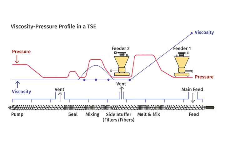
FIG 5 A controlled pressure gradient facilitates sequential downstream unit operations. Viscosity management regulates mixing effects.
Examples of TSE Systems
Premix: A formulation premix can be prepared in a batch mixer and then metered into the TSE. To determine whether a premix is viable, a small batch can be mixed and a put it into a glass jar and shaken; if the formulation doesn’t segregate, then a single feeder is probably acceptable for the mix. The use of powdered resins can help to minimize segregation effects in the hopper.
Premixing should also now be considered part of the “mixing experience.” Higher TSE throughputs are often attainable with premixes; and with careful design of the melting zone to avoid compaction/agglomeration effects, exposure to the high shear stress in the melting region can be particularly beneficial for dispersive mixing. Examples of products that benefit from a premix system include: color masterbatch, flexible PVC formulations and alloys/blends. Small samples are ideal for a premix TSE configuration.
Multiple Feed Streams: Feed streams can be metered into the TSE feed throat with LIW feeders. Pellets and additives are often metered into the main feed throat and/or at various downstream locations. Depending on the batch size and formulation, some premixing may still be warranted.
Sometimes additive particulate compaction phenomena during melting can create agglomerates that are difficult to disperse later in the process, making it preferable to meter into a melt and manage residence-time exposures and the “mixing experience” for different feed streams. The pressure gradient inherent with a starve-fed TSE makes downstream introduction of materials after the melt step possible.
A side stuffer is a device that is commonly integrated with a TSE to introduce fillers, fibers and other materials after plastication. Like a TSE, a side stuffer utilizes twin-screw augers to “push” materials into the TSE process section in order to avoid the high-shear melting zone. That’s why side stuffing is preferred to minimize glass-fiber attrition and to process shear-sensitive fillers, such as flame retardants or chemical blowing agents.
Various liquid injection streams are also common, including both ambient and heated. Reactive extrusion processes (i.e. for thermoplastic urethane) are commonly processed on TSE systems.
Tandem System: SEs string together a series of unit operations to continuously modify, mix and devolatilize polymer formulations. The length/diameter ratio of a corotating, intermeshing TSE is mechanically limited to approximately 60:1 L/D, which restricts the number of unit operations that can be performed. There has been a trend to sequence multiple extruders (both single and co-/counter-rotating TSEs) together in a single system to facilitate L/Ds of 100:1 or more, as well as to integrate extruders with different screw diameters and rpms. Examples might be:
• Mix polymers/additives and develop an homogenous melt in a TSE, then inject supercritical CO2 and pump into a cooling single-screw extruder to make a foamed product.
• Devolatilize 25% of a formulation in a 60:1 TSE and then pump into a crosshead TSE where fillers are mixed, and pump to a gear pump and downstream sheeting operation.
• Reclaim post-consumer waste (i.e., PVB from safety glass) and disperse residual glass, devolatilize moisture, and meter into a second TSE where additional compounding operations are performed.
The opportunities afforded by tandem extrusion systems are largely untapped.
Downstream Operations
Twin-screw compounding systems can be part of pelletizing and direct extrusion systems making a sheet, film, profile or fiber. Front-end devices include screen changers, gear pumps, diverter valves and a wide range of cooling and sizing equipment. Regardless, the main goal of the TSE is to mix the formulation rapidly and efficiently, and without degradation.
Melt-filtration devices are specified to remove undispersed components and clean up the melt before the die. Ultra-fine filtration is possible but invariably causes elevated pressures and temperatures (and maybe degradation). Front-end components should be designed to minimize pressure, have streamlined melt flow paths, and be as short as possible to minimize melt residence time at elevated temperatures.
It’s important to recognize that a well-mixed melt can be degraded after the TSE. An acceptable melt temperature for one product may be unacceptable for another. For instance, the RT in an underwater pelletizing die before quenching the melt is only a matter of seconds and will allow a higher melt temperature without degradation. This is dramatically different from the RT in sheet or film front-end adapters and components that can include a gear pump, screen changer and die, where the RT can be minutes.
There can also be different mixing requirements for the same formulation for different products. For instance, thin structures (i.e., film or fibers) will have a higher dispersive-mixing threshold than thicker-wall products (sheet or molded parts). In extreme circumstances, post-blending after pelletization may be warranted to average out and minimize lot variances. This also can be deemed part of the “mixing experience.”
It has become commonly accepted and evident that the corotating intermeshing twin-screw extruder is a powerful and flexible continuous-mixing device to compound myriad formulations that make the plastic products we see and use every day.
Developments will continue to expand the range and improve the quality of products that are manufactured via TSEs, taking advantage of the unique geometric capabilities inherent with two interacting screws. The metering equipment, twin-screw extruder and downstream systems all should work in concert to control the properties of the final part and manage the “mixing experience.”
ABOUT THE AUTHOR: Charlie Martin is president and general manager of Leistritz, a major supplier of twin-screw extrusion equipment for compounding, devolalization, direct extrusion, pharmaceutical, and other applications. Martin has been in the extrusion industry for more than 30 years, is a member and former chair of the SPE Extrusion Division, and has given dozens of papers at various technical conferences on a range of extrusion topics around the world. Contact: 908-685-2333; cmartin@leistritz-extrusion.com; leistritz-extrusion.com.


Related Content

Processing Megatrends Drive New Product Developments at NPE2024
It’s all about sustainability and the circular economy, and it will be on display in Orlando across all the major processes. But there will be plenty to see in automation, AI and machine learning as well.
Read More
Engineering Resins Compounder Expands to Take on More Scrap
Polymer Resources responds to sustainability push by upgrading plant with grinding and shredding equipment to take on both postindustrial and postconsumer reclaim.
Read More
10 Ways to Improve Twin-Screw Compounding Performance
There are many techniques known to operators and plant engineers for increasing the performance of a twin-screw compounding extruder.
Read More
How to Configure Your Twin-Screw Barrel Layout
In twin-screw compounding, most engineers recognize the benefits of being able to configure screw elements. Here’s what you need to know about sequencing barrel sections.
Read MoreRead Next
10 Ways to Improve Twin-Screw Compounding Performance
There are many techniques known to operators and plant engineers for increasing the performance of a twin-screw compounding extruder.
Read More
Why It's Crucial to Manage Melt-Temperature in a Twin-Screw Compounding Extruder
Managing and controlling melt temperature and degradation in a corotating compounding twin is critical to achieve process optimization. For compounders, it also greatly influences the ability of their molding and extrusion customers to make high-quality parts. Here are the results of research that illustrate this.
Read More
EXTRUSION: Better Mix In Means Better Mix Out
Segregation or de-mixing of polymers and additives can be a big problem in single-screw extrusion. Here’s why it happens, and how to fix it.
Read More