What to Do About Weak Weld Lines
Weld or knit lines are perhaps the most common and difficult injection molding defect to eliminate.
.jpg;width=70;height=70;mode=crop;format=webp)


Weld or knit lines are perhaps the most common and difficult injection molding defect to eliminate. They occur when melt flow fronts collide in a mold cavity. A poor knit line can cause only cosmetic blemishes or it can significantly weaken the structural integrity of a part. Strength at the knit line can be as little as 20% of the nominal strength of the part—or it can be 100% as strong, depending on a host of variables.
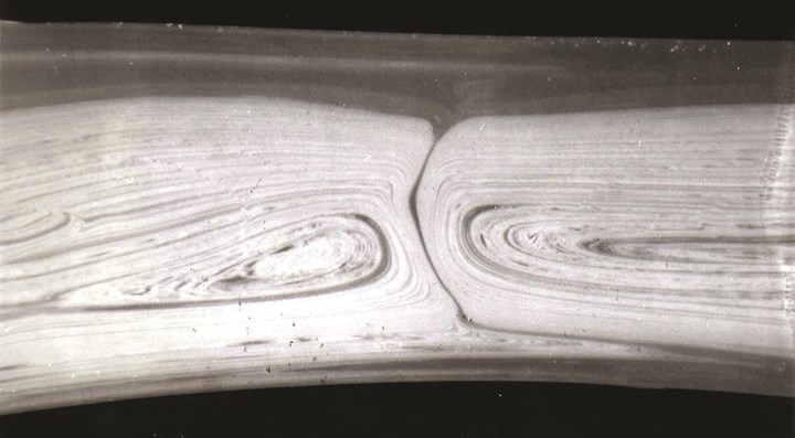
Weld lines occur when part or tool design features—like holes or ribs—split the melt flow and the separate flows do not meld completely when they meet. Weak weld lines occur when there is little or no polymer chain entanglement across the flow-front boundaries.
Weak weld lines have their origins in material choice, part design, tooling, and processing. Some materials are more or less “forgiving” when it comes to weld lines. Part design matters because non-uniform wall thickness can vary the shear and flow rate of the melt front, resulting in a split flow path. Tooling effects include multiple gates into a cavity and projections into the mold like bosses and ribs, as well as holes or depressions, all of which can interrupt and split melt flow into separate fronts. A temperature variation in one section of the mold surface can also create a non-uniform flow front.


Entangling Chains
Material characteristics can affect the knitting of the melt fronts. Weakness results when the polymer chains are only partially entangled across the weld line. Amorphous resins generally provide better weld-line strength than semi-crystalline resins, and a resin with higher flow rate may allow better packing for a stronger weld line. Adding glass fibers also diminishes weld-line strength.
Sometimes volatiles emitted by the resin during processing decrease weld-line strength. Unless properly vented, the gas can hold the flow fronts apart.
Part & Tool Design
Overall, the flow pattern of the plastic as it enters the mold cavity is most important to weld-line strength. Minimizing flow interruptions, and care to place them such that the flow fronts are allowed to meet and flow some distance together to merge properly, are keys to optimizing part performance.
The first rule is to place the gate so that the weld-line location is not in an area of the part that will see high stress during use. Change the gate locations so as to move the weld line to a non-stressed area. If the part features multiple gates, try blocking some gates to reduce the number of potential flow fronts (but get permission first!). Alternatively, try adding an overflow tab, which promotes air venting and molecular chain entanglement.
Optimize weld lines by picking a gate location that allows the polymer to continue to flow and merge after flow fronts recombine.
Another critical rule of part design is a uniform nominal wall to provide a consistent flow front and prevent flow variations upon filling. The type of resin and its shrinkage has important bearing here. Maximum wall-thickness variation allowable for amorphous or low-shrink resins is 25%, while for semicrystalline or high-shrink resins the maximum nominal wall variation is limited to 15%.
Optimize weld-line performance by picking a gate location that will allow the polymer to continue to flow and merge after flow fronts recombine. It is also critical to properly vent the area at and near the weld line. It may be worth the addition of a flow tab that allows the flow fronts to knit a bit better and also acts as a vent for the trapped air as the flow fronts meet. This flow tab has to be cut off, which requires a secondary operation. Bosses, ribs and the like should be in the direction of flow to ease of filling and venting. Other methods to reduce or evacuate trapped air are to use a porous steel insert or vented core pins to improve venting. Vacuum venting is another approach.
If you suspect the mold has a hot spot, allow the tool to sit idle until it comes to a uniform temperature. Compare the first shot with subsequent shots of material. If the flow path is different, the cause is a temperature and cooling issue relating to the tool steel. Check the mold for hot spots and try to achieve uniform cooling. Make sure both mold halves are at equal temperature.
Processing Pointers
Processing can influence the strength and cosmetics of the weld line, but it cannot eliminate the root causes in the material or part or tool design. Low pressure at the flow front does not promote molecular chain entanglement, resulting in poor impact strength. The part may not fully pack out, and if the weld line is in the last area to fill, it may not see much packing pressure.
Trapped air (or volatiles) can prevent good knitting of converging flow fronts. Core pins, “blind” holes, and special mold features can cause air entrapment. Jetting can also be a cause of non-uniform melt flow and weak flow-front melding.
It often helps to increase the injection velocity, decrease the fill time, and increase the shear rate.
Cold flow fronts are not the culprit they are often thought to be. Temperature of the flow front has only a minor influence on molecular chains crossing the flow-front boundary to entangle with chains in the converging flow. While many processors like to raise the melt temperature to improve flow and weld line strength, the increased volatiles coming off the polymer are apt to decrease weld-line strength. Hold this tactic for a last resort.
Instead, it often helps to increase the injection velocity, decrease the fill time, and increase the shear rate, which can lower the viscosity of the polymer during fill and thereby allow for better chain entanglement and better packing. Increasing pack or hold pressure also helps, as well as having longer pack and hold times. Increasing pack or hold pressure helps to eliminate low-pressure conditions at the weld line. Another tactic to promote more chain entangling at the weld line is to raise the mold temperature 10° C (50° F).
Molders should make sure the weld line is formed during the first-stage filling of the part, if possible. Creating a strong weld line during pack and hold often is problematic, as getting flow fronts to meld together is much harder while minimum flow is occurring.
A non-uniform flow front due to non-uniform wall thickness can be remedied by gating into a thick area and providing flow leaders to the thin areas to provide uniform filling. Remember that thicker sections of the part fill preferentially due to lower melt pressures required to fill. Plastic flow will accelerate in thicker sections and hesitate in a thin section. This may allow the polymer to “racetrack” around the perimeter or section of a part and trap air or volatiles. Solutions may be to increase injection rates and round the edge or taper the junction between areas of different thickness. The best answer would be to redesign the part with uniform thickness.
Keep in mind that soft-touch TPE materials are shear-sensitive and can exhibit significant flow lines even without a flow-front interruption. Though not a true weld line, these flow lines are aesthetic defects and do indicate weaker areas of the part. These materials can show a flow line anywhere the shear rate changes, which tends to happen as the flow front spreads.
For a multi-gated part, try valve gates rather than hot tips, if possible, and sequence the actuation of the valve gate in a cascading fashion so the gate only opens after the melt flows past it, resulting in a single melt front.
ABOUT THE AUTHOR
John W. Bozzelli has taught seminars on plastics design and processing for more than 30 years. He has extensive experience in polymer development and processing from more than 20 years with Dow Plastics. He is the founder of Injection Molding Solutions/Scientific Molding in Midland, Mich., a provider of in-plant training and consulting services. Tel: (998) 832-2424 or e-mail: John@scientificmolding.com.
Related Content

Tunnel Gates for Mold Designers, Part 1
Of all the gate types, tunnel gates are the most misunderstood. Here’s what you need to know to choose the best design for your application.
Read More
The Effects of Temperature
The polymers we work with follow the same principles as the body: the hotter the environment becomes, the less performance we can expect.
Read More
The Importance of Melt & Mold Temperature
Molders should realize how significantly process conditions can influence the final properties of the part.
Read More
Understanding Strain-Rate Sensitivity In Polymers
Material behavior is fundamentally determined by the equivalence of time and temperature. But that principle tends to be lost on processors and designers. Here’s some guidance.
Read MoreRead Next

More Gloss, Fewer Weld Lines With Variothermal Molding
A higher mold surface temperature during filling is required to achieve high-gloss surfaces or perfectly replicated microstructures and nanostructures, as well as erasing ugly weld lines. Instrumented tests quantify the results achieved by this process.
Read More
How to Fix Outgassing Problems in Injection Molding
Gas and air entrapment can cause a variety of problems in injection molding, including part burns, short shots, voids and blemishes, even clogged vents. Vacuum venting can solve all these problems, and increase output in the molding process.
Read More
Coping with Weak Weld Lines
Weld lines cause significant reject rates and are a common problem that all molders face.
Read More