
Try Overflow Wells to Remedy Weld Line Weakness
Molding simulations show that adding an overflow well to a part can mitigate the impact of glass fibers on weld-line weakness.


Weld lines are a well-known weak point in molded plastics, though it may be less well known that fiber reinforcements added to strengthen parts overall can exacerbate that weld-line weakness. Can the addition of an overflow well mitigate that disadvantage? Amanda Nicholson, customer success engineer at Moldex3D North America, undertook a simulation study to find out.
Recently hired at plastic injection molding simulation software provider Moldex3D, Nicholson was spurred to undertake the research study following a conversation with a customer experiencing weld-line woes. “I realized weld -line problems are a very common issue for injection molded parts,” Nicholson told Plastics Technology.


The purpose of her study was to simulate the effect on modulus that adding an offset overflow well would have on parts molded from a semi-crystalline, glass-fiber filled thermoplastic. In her research, Nicholson noted that adding glass fibers to a resin can intensify the mechanical property loss at the weld line since the fibers essentially crowd out polymer chains in the melt, reducing the potential for chain entanglement, which imparts strength across the weld line. Nonuniform fiber orientation at the weld line can further contribute to a loss of strength and stiffness.
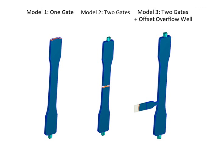
FIG 1: Moldex3D used three tensile bars to simulate the impact of adding an overflow well (model 3) to deal with glass fibers further weakening the weld line created in Model 2 by having two gates. Model 1 with a single gate acted as the control. End of fill (shown in red) shifts from the end of the part opposite the single gate to the center of the part with two gates, to the end of the tab formed by the overflow well in Model 3. (All images: Moldex3D)
In the study, Nicholson used a 35%-glass-filled nylon 66 and three different 1/8-in.-thick ASTM Type I tensile-bar models—one single-gated at the bottom, one with two gates (top and bottom) and a third with two gates plus an offset overflow well on its side (Fig. 1). The overflow well was 66.67% of the wall thickness. “In this case, the overflow well was quite large relative to the small part,” Nicholson says. In addition to measuring two-thirds of the wall thickness of the part, the length of the tab was extended to ensure there was sufficient flow through the weld line to help reorient the glass fibers. With this design, the overflow tab made up 9% of the overall part, excluding the gate and runner system. “The overflow tab should be optimized for each part,” Nicholson notes, “and this value will vary greatly depending on the part size.”
In simulating the three tensile bar variations, end of fill (EOF) occurred at the end of the bar opposite the lone gate in the first model (Fig. 1); at the weld line in the center of the bar in the second model with gates on either end, and in the overflow well in the third variation. Nicholson notes that having EOF in the well is important, since it means material will still flow through the center of the part after the weld line first forms. Referred to as “underflow,” this filling acts to reorient the glass fibers, which increases major modulus along the length of the part (watch an animation of underflow). “If the overflow well were to fill before the weld line was formed, no underflow would occur,” Nicholson states. While adding an overflow well can shift the weld-line’s location, in this instance it had no affect.
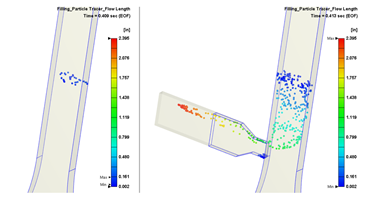
FIG 2: Moldex3D’s Particle Tracer shows the flow length of particles originating from either the melt entrance or the weld line.
Nicholson was able to verify the “underflow” by utilizing Moldex’s Particle Tracer function (Fig. 2). This function tracks the movement of imaginary discrete “particles” of melt during part filling. While the second model showed negligible particle flow length after weld-line formation, the third model showed movement of particles through the center of the part into into the overflow well, which serves to change glass-fiber orientation and increase polymer chain entanglement. Moldex’s Fiber Orientation modeling also verified a beneficial effect of the overflow well. Figure 3, the fibers in the single-gated part show a high degree of orientation along the direction of flow. In the double-gated part, the fibers tend to re-orient perpendicular to the major flow direction at the weld-line location, contributing to the weakness at that spot. With addition of the overflow well, the simulation shows strong flow-direction orientation of glass fibers through the weld line.
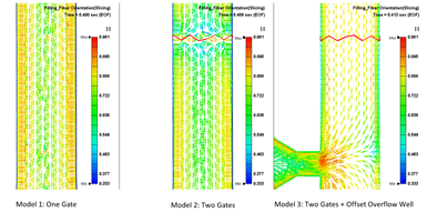
FIG 3: In the three bars, Moldex3D shows how the different designs impact fiber orientation, with a high degree of orientation at the weld line in the third model with the overflow well.
Nicholson used Moldex3D to simulate the value of the major modulus (stiffness in the direction of flow) for the three tensile bars (Fig. 4). Compared with the control part (single gate and no weld line), the double-gated part showed a major-modulus reduction at the weld line from 1,376,800 psi down to 898,593 psi—a roughly 35% reduction in stiffness. The addition of the overflow well increased the major modulus at the weld-line location to 1,155,520 psi—just 16% less than the control tensile bar.
At Times Unavoidable
Nicholson says the purpose of the study was to address any glass-filled part that has weld lines, whether they’re the result of multiple gates, features like holes, or non-uniform wall thicknesses. “It is ideal to design parts with no weld lines,” Nicholson says, “but that is not always realistic.”
If an overflow well is the best option, Nicholson notes there are multiple methods to incorporate them into a part. “The best-case scenario would be to design it into a part feature or put it in a non-cosmetic, non-functional area where it isn’t required to be removed,” Nicholson advises. Short of that, the well tab could be taken off manually or removed automatically, via a degating system.
If an overflow well is not an option, and the usual tricks deployed to orient fibers in a weld line—such as increasing mold and melt temperature, boosting pack pressure or adding venting—don’t work, there are other options.
“Gate-location changes, flow leaders, flow restrictions and sequential valve gates are other examples of strategies that can be employed to influence weld-line location and fiber orientation,” Nicholson notes.
(Editor’s note: For comments on weld lines and overflow wells by injection molding consultant John Bozzelli, visit https://short.ptonline.com/weldline. To read more on this topic, you can also check out this research article in Polymer Composites.)
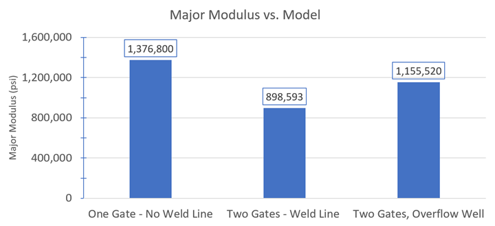
FIG 4: Moldex3D simulations show that compared with the control bar with a single gate, the major modulus of the third model with an overflow well showed less of an impact from the creation of a weld line.


Related Content

50 Years of Headlines … Almost
I was lucky to get an early look at many of the past half-century’s exciting developments in plastics. Here’s a selection.
Read More
How to Achieve Simulation Success, Part 2: Material Characterization
Depending on whether or not your chosen material is in the simulation database — and sometimes even if it is — analysts will have some important choices to make and factors to be aware of. Learn them here.
Read More
Injection Molding Simulation Meets the Real World
Direct data interface between molding simulation and the injection machine links the computer model to the real-world process. This can improve results from product and mold design through ongoing production. A case study demonstrates these benefits for automotive components in a family mold.
Read More
How to Achieve Simulation Success, Part 1: Model Accuracy and Mesh Decisions
Molding simulation software is a powerful tool, but what you get out of it depends very much on your initial inputs. Follow these tips to create the most successful simulation possible.
Read MoreRead Next

The Awful Truth About Weld Lines
As everyone knows, weld lines are weak points. What’s less well known is just what’s going on inside that weld line on a microstructural level. Here’s a close-up look at some nasty little secrets.
Read More
Faster Mold Simulation Arrives
Moldex 3D Version R16 offers dramatic improvements in speed plus greater simplicity and ease of use and new simulation capabilities.
Read More
Upgraded Simulation Package Adds Nozzle Zone & Conformal Cooling ‘Wizards’
Wizards assist conformal-cooling layout and simulation of melt compression in the nozzle in Moldex3D 2021.
Read More