
What’s Controlling Your Cycle Time? Part 1
Follow these guidelines to maximize your profits.
.jpg;width=70;height=70;mode=crop;format=webp)


My strengths are in part design, mold design, mold debugging, part quoting and project management. But I am a wannabe processor. That’s because tooling and molding are so intertwined. Without a thorough understanding of both fields, solving molding problems can be challenging and often frustrating. I reached out to John Bozzelli and asked if he would collaborate on this article to help bridge the two fields. The goal of this article is to help those involved in processing and troubleshooting an injection mold to produce the best parts possible at the fastest possible cycle time.
To keep the length of this column to minimum, many of John’s Plastics Technology columns, as well as some articles authored by Phil Burger of Burger and Brown Engineering, are referenced for additional information. While this series will go into a lot of detail, it’s nothing compared to the multitude of additional factors a processor should consider when trying to establish the best process. I am only going to discuss those items that effect the cycle time.


Many of you know the age-old saying in our industry that that we don’t sell molded parts, we sell press time. That’s not entirely true. The fact is we sell estimated press time, and that is where a molder can either be very profitable or lose his shirt.
Molders sell parts based on estimated cycle times.
At the very start of any project, before a mold is even built, or before a molder receives an existing mold from a customer, the parts have to be quoted. There are at least 14 different factors to be considered when estimating the cycle time. Instead of rehashing them here, they are well covered in the February 2021 Tooling Know-How column, Get Better at Quoting Injection Molded Parts–Part 3. Of those 14 factors, only the cycle time is an estimate—and all too often, a guess-timate.
Even if a flow analysis is performed, the cycle time is still a guess-timate. While a flow analysis may be able to give a fairly accurate prediction of the required fill time and cool time, it cannot predict how well the mold, the machine and, in many cases, the operator will function. It also can’t predict how well the process will be established on any given machine—especially an older model. Therefore, the goal in quoting any injection molded part is to be very critical of the estimated cycle time and add a small percentage to cover any unforeseen issues without pricing yourself out of the job.
If the annual quantity of parts is on the low side, you are not going to lose too much profit if you underestimate the cycle time. But for very high-volume jobs, that cycle-time estimate better be very accurate or you are really going to get hurt. In the real-estate business, the slogan is location, location, location. In our business the slogan should be cycle time, cycle time, cycle time.
After the mold is built, or an existing mold arrives at your dock, it’s time for its first sampling. This is when you find out if you are going to make any money or not. This is also when a lot of the options to improve the cycle time, such as having the ideal part and mold design, are relatively fixed variables that cannot be changed and must be dealt with the best you can.
The Extra Mile
Rule Number 1: Never tell the processing technician what the job was quoted at. Let him or her do their job and establish the best possible process. If they ask why, just say, “I trust you know how to do your job.”
Rule Number 2: Tell the processing tech what the job was quoted at after he or she establishes a process if its cycle time ends up being longer than the quoted cycle. Unfortunately, it is all too common to have needlessly extended cycle times when it doesn’t affect the processing tech’s paycheck. (Unless the company is an ESOP, it rarely does.) This is when a little diplomacy is in order. Ask the processor what they believe to be the reason(s) for the longer-than-quoted cycle and offer to help overcome them. This is where a knowledgeable processor is worth their weight in gold—especially when they go the extra mile.
Almost every processor I know starts out by requesting a copy of the material specification sheet. Even if they have used a commodity resin a million times, they know that every brand and grade have differences—some minor, some major. They start with the manufacturer’s recommendations on the barrel temperatures, mold temperature, screw rpm, backpressure, etc. (That’s assuming the material data sheet even has recommendations for machine parameters. Many don’t.) Then they apply their molding knowledge to establish a repeatable process.
A knowledgeable processor is worth his weight in gold.
If Quality Control and the customer approve this established process, many processors think their work is done and they did another great job. Unfortunately, nothing could be further from the truth. There is a very strong possibility they left tens of thousands of dollars on the table because they didn’t go that extra mile. There is also a strong possibility that the process that once made good parts will start to spit out bad parts a few hours later—usually on an off shift. That’s when the knob turning and button pushing starts—negating the previously “established” process. With that said, let’s take an in-depth look at how to reduce the cycle time of a mold, have a more robust process, and improve the quality of the molded parts.
Elements of a Mold’s Cycle
The overall cycle time of a mold is the combined times of the 11 components listed below. When trying to minimize cycle time, consider each of these components individually. Also consider how any adjustments to one component can or will affect the other components, because they are all interrelated in one way or another.
1. Mold closed and lock-up time.
2. Fill or inject time.
3. Pack and hold (gate freeze or unfreeze) time.
4. Screw delay or suck-back before rotation time (pre-decompression).
5. Screw recovery and plasticating time.
6. Screw decompression or suck-back after rotation time (post-decompression).
7. Cooling time.
8. Cooling delay or idle time before mold-open time.
9. Mold-open time.
10. Part ejection (and robot capture) time.
11. Ejector (and robot) retraction time.
Ejection Temperature
I want to begin this discussion with evaluating the time required to cool the part. Cooling is typically the greatest percentage of the cycle time for any mold. In fact, it can be 80% or more of the cycle time. Yet, all too often, cooling is inadequately considered in the part design, mold design, and processing stages—especially the processing stage. But now the part is already designed, and the mold is already built. So, what can be done to the process to make sure the cooling time is as efficient as possible?
The first place to look is the part-ejection temperature. I am always amazed at how many molders eject parts that are the same temperature as their cooling tower, or colder. Some processors will say that as the parts stack up under the mold, or at the bottom of a chute, the cumulative amount of heat still emanating from the parts can cause some internally stressed parts to warp. That’s what conveyors and cooling fans are for! Some will say the parts are fine, but portions of the runner are still molten, and they stick to the parts. That’s what a sprue picker or robot is for! I have seen nylon parts with drastically extended cycle times because the operators complained the parts were too hot. That’s what gloves are for! Everyone has their excuses for extended cycle times, but very few have valid reasons for them.
The accompanying table shows typical ejection temperatures for various materials, based on the precision of the parts to be molded. Of course, these values are for reference only. They can vary considerably based on the part geometry, especially the wall thickness. While you can eject a thick-walled part without any issues or deformation, you will start to feel it heat up and possibly warp right in your hand. That’s because the center of the part is still molten, and the heat is still migrating to the surface.
When speaking about ejection temperature, we are speaking about the part—not the runner. You don’t sell runners. The best way to check the temperature of a molded part is with an infrared (IR) thermal-imaging camera. Laser targeting (pinpoint) IR thermometers are not as accurate or informative. Check the part temperature right before it is ejected, or immediately thereafter.
Figure 1 shows a thermal image of a center-gated part having a uniform wall thickness. As expected, the gate, or start of the material flow, is the hottest area on the molded part. Also notice how some fingers quickly sucked the heat out of the part. These cameras are that accurate – and informative. Hot spots on a part often control the cooling time. Anything that can be done to the mold to reduce the hot spot, such as a copper-alloy insert or a better cooling circuit, can save you several seconds of cycle time.
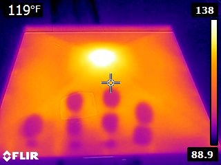
FIG 1 Thermal image of a molded part. (Photo: J. Fattori)
It is also helpful to take a thermal image of the mold (Fig. 2)—or at least feel for hot spots with your hand or surface pyrometer—immediately after the mold opens. Unfortunately, there is usually a problem with taking thermal IR images. Steel molds are highly reflective and typically give bad temperature readings—even when the parameters are adjusted to measure metal rather than plastic. There are aerosol sprays available, such as Magnaflux SKD-S2, to coat the surface of the mold, which reduces the steel’s reflectivity and gives much better results. However, it is often easier to just put some dull-colored masking tape on the areas of interest.
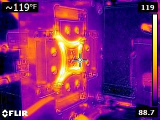
FIG 2 Thermal image of a mold. (Photo: J. Fattori)
Even though they aren’t what you sell, it is not uncommon for the sprue and runner to control the cycle time. The issue is typically located at the intersection of the sprue, runner and cold well. That’s where the thickest section of material is in the mold, as shown in Fig. 3.
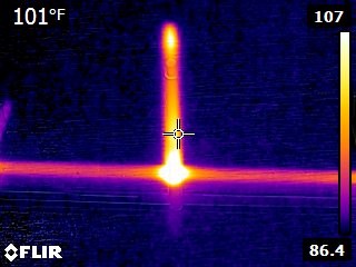
FIG 3 Thermal image of a “cold” runner. Photo: J. Fattori
If the cooling time is too short, the cold well can separate from the runner, as shown in Fig. 4A, or the sprue can separate from the runner, as shown in Fig. 4B. When the sprue separates from the runner it can stay in the cavity when the mold opens. You should know what happens on the next shot.
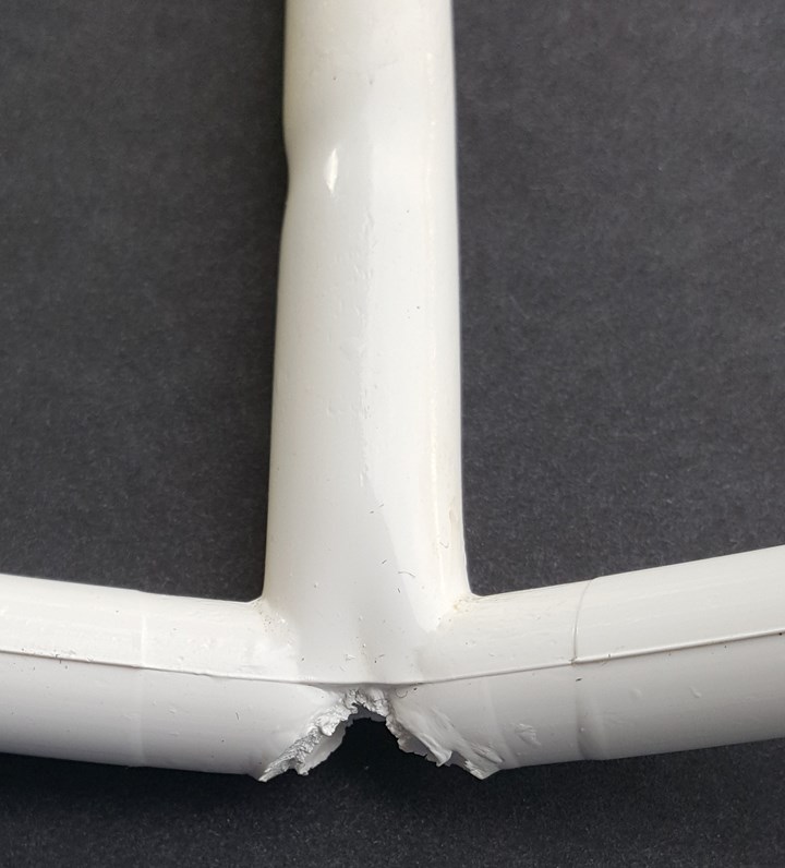
FIG 4A If the cooling time is too short, the cold well can separate from the runner, as shown here.
(Photo: J. Fattori)
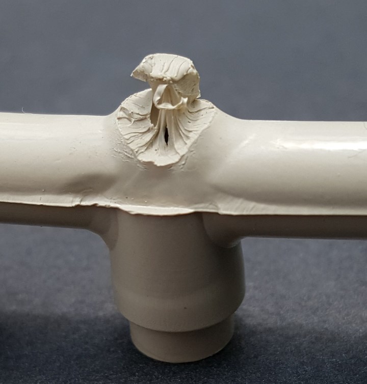
FIG 4B If cooling time is too short, the sprue can also separate from the runner. When this happens, the runner can remain in the cavity when the mold opens. (Photo: J. Fattori)
So, what can be done to improve the situation and reduce the cycle time? Some suggestions are:
• Make sure the sprue bushing is highly polished for most materials, but sand-blasted for polyolefins and elastomerics.
• Replace the sprue bushing with one having a smaller inner taper.
• Recess the sprue bushing to make it shorter, but never let the head of the bushing rest against a cavity insert or runner bar.
• Replace the cold sprue bushing with a hot sprue bushing.
• Add gussets where the sprue intersects the runner, and where the runner intersects the cold well (Fig. 5).
• Add stiffening ribs to the runner, especially on three-plate molds, to prevent curling and ejection issues.
Next month, John and I will look at other important areas to help reduce a mold’s cycle time.
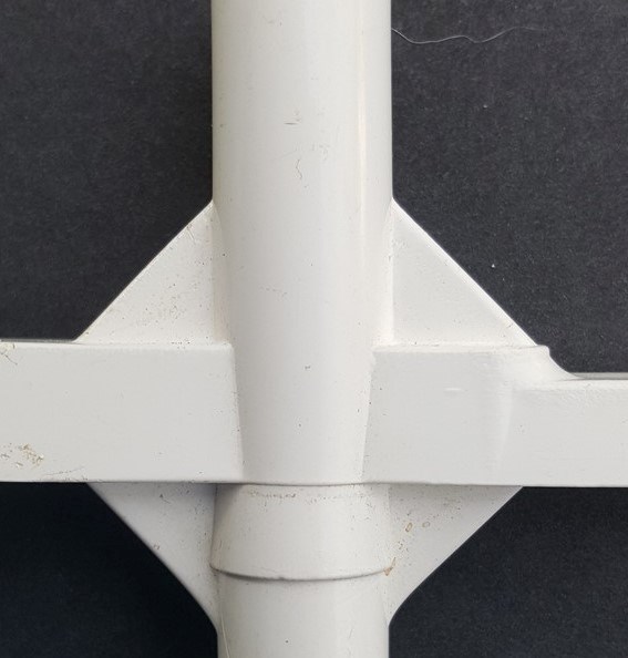
FIG 5 Sprue and cold-well structural gussets. (Photo: J. Fattori)
ABOUT THE AUTHORS: Jim Fattori is a third-generation molder with more than 40 years of experience in engineering and project management for custom and captive molders. He is the founder of Injection Mold Consulting LLC in Pennsylvania. Contact: jim@injectionmoldconsulting.com;
injectionmoldconsulting.com.
John Bozzelli is the founder of Injection Molding Solutions (Scientific Molding) in Midland, Mich., a provider of training and consulting services to injection molders, including LIMS, and other specialties. Contact john@scientificmolding.com; scientificmolding.com.


Related Content

Best Methods of Molding Undercuts
Producing plastics parts with undercuts presents distinct challenges for molders.
Read More
Back to Basics on Mold Venting (Part 1)
Here’s what you need to know to improve the quality of your parts and to protect your molds.
Read More
How to Mount an Injection Mold
Five industry pros with more than 200 years of combined molding experience provide step-by-step best practices on mounting a mold in a horizontal injection molding machine.
Read More
How to Start a Hot-Runner Mold That Has No Tip Insulators
Here's a method to assist with efficient dark-to-light color changes on hot-runner systems that are hot-tipped.
Read MoreRead Next

INJECTION MOLDING: Develop Guidelines—Not Strict Procedures— For a Robust Molding Process
‘Fool-proof’ dos and don’ts will prove foolhardy in a process with so many variables. You aren’t slinging burgers.
Read More
Minimize Screw Recovery & Cycle Times
There are hundreds of details you must identify and control to run a successful molding plant. One that is almost always at the top of the list is optimizing cycle time. Shorter cycles that make acceptable parts improve profits.
Read More
Plasticating Rates: Your Profits Are at Stake
To get the best cycle time you need the right machine, and few molders take the time to specify this critical component of the process.
Read More