What’s Controlling Your Cycle Time? Part 2
Follow these mold-cooling guidelines to maximize your profits.
.jpg;width=70;height=70;mode=crop;format=webp)


Molds are designed with a set number of cooling circuits. My definition of a cooling circuit is a little broader than most. I consider a circuit a combination of the individual components between the inlet and outlet manifolds on the temperature controller (thermolator), cooling tower, or chiller. Therefore, a circuit would include the fittings on the manifolds, the fittings on the hoses, the hoses themselves, the fittings on the mold, the cooling channel inside the mold, as well as any diversions within the cooling channel, such as a baffle, bubbler, thermal pin—even a 90° bend. Like a chain, the circuit is often only as good as its weakest link. To minimize cycle time, it is vital to ensure that the entire cooling circuit and the coolant flowing through it are used to their maximum efficiency.
Always check that the mold was set up correctly.
The first thing I recommend doing is to check that the mold was set up correctly. Look for anything that could restrict the flow or increase the pressure of coolant going to and from the mold. Are the ball valves in the manifolds the proper size? Do the hoses have a sufficient inside diameter? Are any of the hoses excessively long? Do any of the hoses have a sharp bend in the line? (Hoses have a minimum bend-radius rating.) Do any of the fittings on the hoses have internal automatic shutoff valves? Most suppliers say there is a “minimal” loss of pressure and flow rate with valved fittings. Figure 1 suggests that is not the case.


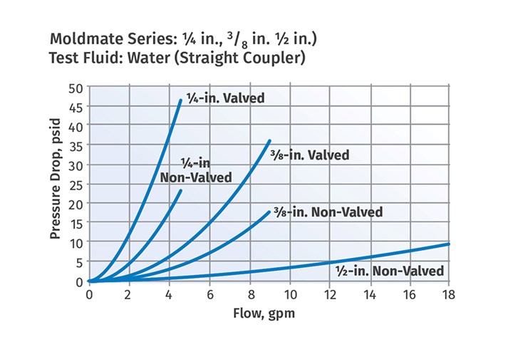
FIG 1 Pressure loss and flow rates for water-line fittings. (Source: Parker Hannifin Corp.)
The amount of water flow through any component, such as a hose, fitting or water channel, depends on the inside diameter, the overall length, and the pressure applied to the water. Therefore, to have an efficient circuit, you want the largest diameters and the shortest lengths possible, so that you can minimize the required pressure.
Cooling-channel buildup will extend the cycle time.
If it’s a mold you inherited and it looks like it has some miles on it, it would be wise to remove the water fittings and inspect the cooling channels for a buildup of scale, rust, calcium oxide, lime or biofilms, as shown in Fig. 2. Just a few thousandths of an inch of any of these deposits will insulate the walls of the channel and dramatically reduce the thermal conductivity, which will absolutely extend the cycle time. In fact, a buildup of a mere 0.015 in., or the thickness of four sheets of paper, can increase the temperature of the steel by as much as 50° F. This is another reason to have a preventive mold-maintenance plan in place—especially for molds that contain small flow passages, such as baffles and bubblers.
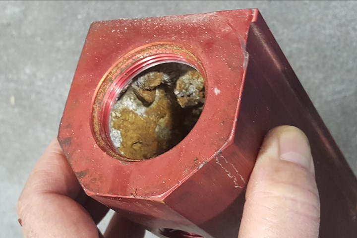
FIG 2 Calcium buildup in a cooling circuit. (Photo: J. Fattori)
Check the water-fitting hole diameters.
While you have the fittings off, compare the inside diameter of the fittings to the inside diameter of the bore holes in the mold. The holes in the mold should be at least the diameter of the fitting but are usually much larger. That’s because water-line channels are usually the same size as the tap drill used for the NPT fitting—as shown in Fig. 3. However, a mold designer will often use smaller diameter holes due to the part geometry, ejector-pin locations, etc. I recommend checking these sizes even on new molds. Don’t assume the moldmaker installed the most efficiently sized fittings—particularly if they are ¼-in. NPT or larger.
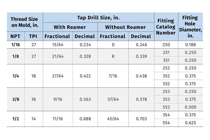
FIG 3 Standard mold water-fitting sizes. (Data source: Holo-Chrome)
Standard fittings are available with different inside diameters, as shown in Fig. 3. They are typically referred to as 200-, 300- and 500-series fittings. Be careful when purchasing water fittings. Some mold-component suppliers’ catalogs don’t even specify their bore diameters! You want to use the largest orifice size available for a given bore diameter in the mold. Undersized fittings do not necessarily restrict the flow of water, and since they are only ¾ in. to 2 in. long, there is not a significant pressure loss going through them.
The problem is that hoses used on smaller-series fittings have smaller inside diameters. Since hoses are very long, the amount of pressure drop can be considerable, especially if the mold temperature controllers have centrifugal pumps. Centrifugal pumps pump less as the pressure goes up, whereas positive-displacement pumps maintain gallons per minute (gpm) flow. The combined increase in pressure may end up exceeding the capacity or horsepower of the water-source pump. That condition would extend the cycle time or start to produce rejects because the cooling requirements are pressure limited.
Now check the hoses for the individual water lines. Are they connected correctly to the supply and return manifolds? You’d be surprised how often they’re not. The Inlet and Outlet cooling channels need to be identified on the surface of the mold. It is absolutely ridiculous and a complete waste of time for a setup man to blow air through each unidentified hole to see what hole the air exits from. Waterlines are typically hand stamped or occasionally engraved 1IN, 1OUT, etc. Color-coded and numbered tags are commercially available for this purpose. They can be mounted flush to the outside of the mold and give it a professional appearance. You might also try Dykem Metal Stain (not layout fluid) to color code the fittings red and blue. One trick John Bozzelli recommends for ensuring proper hose connection is to use female fittings for the inlets, and male fittings for the outlets.
The Inlet and Outlet cooling channels need to be identified on the surface of the mold
Hooking up the water lines to a mold that has a bubbler, also known as a cascade or fountain, is critical for it to function correctly. The water inlet should flow into the bubbler tube first. The outlet is therefore at the end of flow on the outside of the tube. If the hookup for water flow is reversed and the tube is at a slight angle or bent, you will get uneven cooling in the bore hole. You want the water exiting the end of the tube to blast against the bottom of the bore hole, which is often where you want the best cooling (top of a core—opposite a gate). If a mold has any baffles or bubblers with a flow area of 1/8 in. or less—about the size of a single plastic pellet—it is a good idea to add a non-restrictive, in-line particulate filter to those channels.
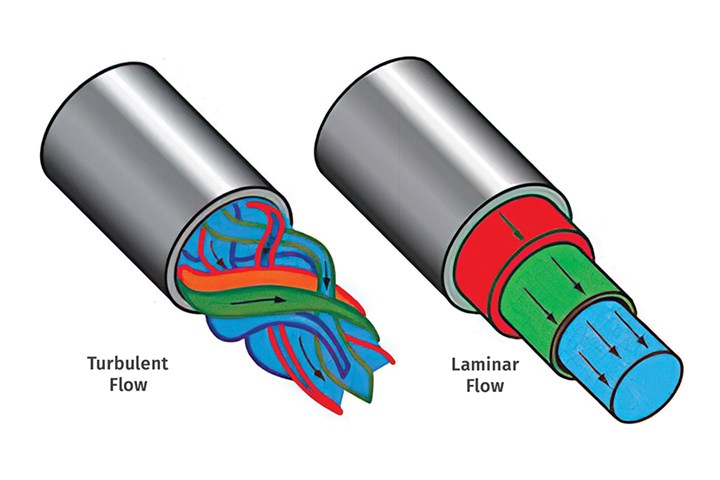
Now it’s time to perform a scientific cooling analysis on the mold. This includes checking to make sure the water flow in each circuit is turbulent, rather than laminar (as shown in Fig. 4), and that a temperature difference, or Delta T, between the inlet and outlet of each circuit is 4° F or less. Visually checking the flow of water squirting into a 5-gal bucket is not very accurate or scientific. The only thing that really tells you is whether the hoses are connected (not necessarily correctly) and whether there are any blockages—nothing else.
To check whether the water in each circuit has turbulent flow, you will need at least one flow meter. The basic mechanical types are not very expensive. They can cost as little as $35. If you add a ball or gate valve (which converts a flow meter into a combination flow meter and flow regulator), a temperature sensor and a pressure gauge, the cost can start at around $85. I recommend getting two flow meters with built-in temperature and pressure gauges. That will save you from having to use a pyrometer or infrared (IR) temperature gauge to check the inlet-minus-outlet temperature differential. And you can see whether there is an unacceptable pressure loss in each circuit—for any number of reasons. Just make sure you get a meter with a gpm flow rating sufficient for your needs.
Measuring the pressure loss through a cooling circuit is not a critical requirement of scientific cooling. It is more of a reality check. If you measure a high pressure loss, there could be a reason for it—like scale buildup or incorrectly sized flow channels to a baffle or bubbler.
Electronic flow meters are typically more accurate than the mechanical versions. Some models include the ability to remotely monitor both the flow rate and temperature in real time. These higher-end devices are ideal for process validation and lights-out operations. It’s also nice to know when a temperature controller decides to quit, or was never turned on, long before the in-process quality-control inspector brings you rejects full of heat waves.
Measuring the pressure loss through a cooling circuit is not a critical requirement of scientific cooling. It is more of a reality check.
What should the flow rate be for a cooling channel in a mold? That depends on the flow area, the shape of the flow area, the coolant temperature, whether the coolant contains ethylene glycol, and the desired Reynolds number. Start by determining what is the largest flow area in each circuit. For example, let’s say the inlet and outlet water fittings have ¼-in. NPT fittings with a 0.250-in. orifice diameter, and the water-line bore diameter in the mold is 0.422 in. Since the water-line bore diameter has the largest flow area, that’s the value you use in the calculations to determine the necessary flow rate.
You use the largest flow area because it will require the highest gallons per minute of water flow to be turbulent. Why will it require the highest gpm? Because the speed of the water flowing through the smaller flow areas, such as the water fittings, will be much faster. In the larger flow area, the speed is much slower and therefore less turbulent. There is no need to consider the inside diameter of the hoses. You don’t care if the flow in them is turbulent or not.
Now you need to input some variables into a Reynolds number calculator. Don’t get excited. It’s not difficult at all. Burger and Brown Engineering has a free calculator (smartflow-usa.com/turbulent-flow-rate-calculator). The Reynolds number is a non-dimensional or unitless value. If you want to get technical, the Reynolds number is the ratio of inertial forces to viscous forces within a fluid that is subjected to relative internal movement due to different fluid velocities.
Expert opinions vary widely as to what value is considered turbulent. It seems 2000 to 3500 is considered transitional—where a fluid starts to become turbulent. Therefore, most people agree that 4000 is the minimum value you want, but that 5000 to 6000 is ideal to guard against any fluctuations in the process, as depicted in Fig. 5. Unless you are trying to shave fractions of a second off the cycle (for example, with cap and closure molds), anything greater than 6000 is not really necessary and a waste of energy.
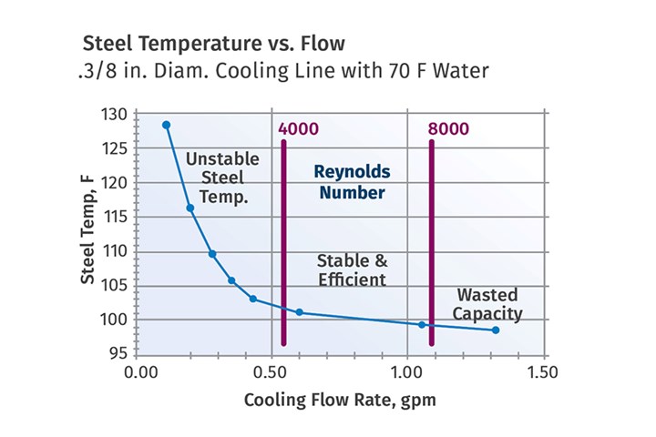
FIG 5 Turbulent vs. laminar flow. (Source: Burger & Brown Engineering)
After you have determined the required flow rate for each circuit, you need to add them all up to see whether your chiller, tower or temperature control unit (TCU) has sufficient output in gallons per minute (gpm) to meet the flow requirements of the mold. See Bozzelli’s April 2010 and June 2013 columns, Don’t Neglect Cooling, and Pay Attention to Heat Transfer, for a better understanding of how to add up the flow rates of multiple cooling circuits.
Water always takes the path of least resistance.
If there are cooling channels in the mold with different internal diameters and flow areas, and you haven’t plumbed all of the circuits in series (end to end)—which is rarely done—you are probably going to have a problem. Series plumbing requires a significant amount of pressure and flow rate (gpm) to push enough water through to get turbulent flow. What’s worse is that the Delta T, or temperature differential between the inlet and outlet, is often more than 4° F. The alternative, and more common method, is to plumb the mold with multiple parallel lines connected to water manifolds.
The problem is that water always takes the path of least resistance, which is why it is essential to force the water where it is needed most. Let’s say you have some circuits with a 1/8-in. NPT channel and others with a ¼-in. NPT channel. If you plumb these circuits in parallel, the ¼-in. circuits are going to get most of the water flow. The 1/8-in. circuits will get less flow and will possibly not be turbulent. The problem is even worse with molds having restrictive baffles or bubblers within the circuits. Those circuits are often the ones that need the most cooling because they are in a thin insert, cam, or other hard-to-cool area. Other than plumbing the entire mold in series, the only way to overcome this problem is to install flow regulators on the less restrictive circuits, or to use a positive-displacement type of pump. A short video on YouTube demonstrates how flow regulators are used to achieve turbulent flow in molds with different sizes of water lines.
Optimizing the flow rate in each cooling circuit will reduce the total volume of water required, which saves energy and money.
Both methods cited above can add up to a fair amount of money. Flow regulators are often the cheaper option, but positive-displacement pumps will help you sleep at night. In the last decade, several high-tech temperature controllers have become available, offering molders capabilities they have only dreamed of before. If you are a serious molder with dimensionally critical parts or have molds that are basically welded to the platen, running 24/7/52, I suggest you read Matt Naitove’s May 2015 Close-Up A New Name & New Dimension in Mold Temperature Control. You may never buy a temperature controller with a centrifugal pump again.
More importantly, optimizing the flow rate in each cooling circuit will reduce the total volume of water required, which saves energy and money. Many machines come with flow regulators installed on the back side of the machine—those vertically mounted clear tubes or sight glasses with a float inside and a dial or regulator valve to vary the flow. Yes, the ones that turn brown inside after a few months and are not often used.
As mentioned before, the temperature of the coolant flowing into the mold minus the temperature of the coolant flowing out of the mold should not be greater than 4° F. This is called the Delta T. For critical parts, such as in the medical or automotive industries, a Delta T of 2° F or less is preferred—if not required.
One of the variables you need to enter in a Reynolds-number calculator is the water temperature. That’s because the water temperature affects the flow rate needed to achieve turbulent flow. The colder the water, the greater the flow rate needed. When entering the temperature into the calculator, keep in mind the temperature variation of the system supplying the coolant. For example, chillers can vary in temperature as their compressors cycle on and off based on their setpoint. Therefore, use a value slightly higher than the setpoint temperature.
To maximize the heat transfer between the part and the steel mold, the parts need to be sufficiently packed out. When parts are under-packed, they can shrink away from the cavity steel, which reduces the heat transfer. This is especially prevalent in thick-walled parts. This is where the gates need to be deep enough to remain open so the machine can continue to inject material into the shrinking cavity. While deep gates extend the gate-seal time, they reduce the more important overall cooling time and shorten the cycle time.
The temperature of the production facility doesn’t need to be a comfortable 72 F. It only needs to be cool enough to lower the dewpoint.
Most molders do not have air conditioning in their production facility. When the dewpoint in the summer months is high, the molds often “sweat”—literally forming water droplets on the parting line, which can show up on the parts. But what does this have to do with mold cooling? Many processors will use a warmer-than-recommended water temperature in their molds to prevent mold sweating, which extends the cycle time. They say they must establish a process based on the summer temperature conditions. So, nine months of the year they have needlessly extended cycle times.
Management may not want to spend a small fortune to install air conditioning in a production area, which will also increase their monthly electric bills. What they don’t realize is that the temperature of the production facility doesn’t need to be a comfortable 72 F. It only needs to be cool enough to lower the dewpoint, so that the cycle times are at their minimum—all year long. Basically, the air conditioner is used strictly as a dehumidifier.
I would love to see someone crunch the numbers to determine the ROI on installing air conditioning in a molding facility. I am tired of seeing dust-encrusted fans mounted on pedestals or walls, trying to keep operators from melting. I bet if you factor in the added electrical cost of these fans, as well as the increased turnover rate of employees, and all of the other cost factors, the ROI will be well justified.
Next month, John and I will look at additional important factors to help reduce a mold’s cycle time.
ABOUT THE AUTHORS: Jim Fattori is a third-generation molder with more than 40 years of experience in engineering and project management for custom and captive molders. He is the founder of Injection Mold Consulting LLC in Pennsylvania. Contact: jim@injectionmoldconsulting.com;
injectionmoldconsulting.com.
John Bozzelli is the founder of Injection Molding Solutions (Scientific Molding) in Midland, Mich., a provider of training and consulting services to injection molders, including LIMS, and other specialties. Contact john@scientificmolding.com; scientificmolding.com.-
Related Content

The Effects of Temperature
The polymers we work with follow the same principles as the body: the hotter the environment becomes, the less performance we can expect.
Read More
How to Select the Right Tool Steel for Mold Cavities
With cavity steel or alloy selection there are many variables that can dictate the best option.
Read More
Why (and What) You Need to Dry
Other than polyolefins, almost every other polymer exhibits some level of polarity and therefore can absorb a certain amount of moisture from the atmosphere. Here’s a look at some of these materials, and what needs to be done to dry them.
Read More
A Simpler Way to Calculate Shot Size vs. Barrel Capacity
Let’s take another look at this seemingly dull but oh-so-crucial topic.
Read MoreRead Next

What’s Controlling Your Cycle Time? Part 1
Follow these guidelines to maximize your profits.
Read More
Pay Attention to Heat Transfer
Money will be lost if cooling is not done right.
Read More