
Extrusion: Important Polymer Melting Equations for Extrusion Processors
The more you know about what happens in a screw, the more you’ll be able to work with your supplier to optimize design.
.jpg;width=70;height=70;mode=crop;format=webp)


A major step in the design of extrusion screws took place in the early 1960s as a result of research work by Western Electric Co., the former manufacturing side of the Bell System and later AT&T. Some of the more basic aspects of screw design—such as output and power calculations—had already been developed by others, but a more complete analysis of feeding, melting and pressure development was still underway at that point.
I remember doing multiple screw “push-outs” of full screws in the lab trying to verify some of those theories, but the amount of calculations involved for a whole screw was so complicated it was completely impractical without a computer. The wider availability of computers at that time allowed for a more complete analysis of what happens as polymer progresses down the screw channels. The formulas for these programs were adjusted, readjusted and then readjusted again by the Western Electric researchers until they closely matched actual lab results. This work evolved into a full-length computer analysis. But even without a computer simulation system, a great deal can be learned from the formulas developed for the computer programs.


In a conventional screw, the melted and unmelted polymer coexist in the same channel, making the analysis very complicated. Melting occurs primarily at the barrel wall, due to shear between the solids in the rotating screw and the stationary barrel wall. Heat transferred from the barrel constitutes a relatively small part of the necessary energy once the screw is in operation.
Melting occurs primarily at the barrel wall due to shear between the solids in the rotating screw and the stationary barrel wall.
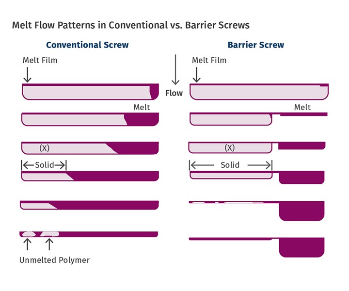
As the accompanying illustration shows, in a conventional screw the melt (or “melt pool”) width increases as it moves down the barrel; eventually melt fills most of the channel as melting progresses. Barrier-type screws are designed to allow the melted polymer to flow over the increased clearance of the barrier flight and accumulate in a separate channel, thereby keeping the area where unmelted polymer is in contact with the barrel wall quite constant. As a result, the melting rate is also constant throughout the barrier-section length, unlike a conventional screw design, which generally has decreasing melting rate due to the enlarging melt pool as material moves down the screw.
Equations for many aspects of extrusion screws were developed and later published by Imrich Klein and Zehev Tadmor, two of the principal researchers at Western Electric, in their book Engineering Principles of Plasticating Extrusion. I used programs developed by them for a number of years before developing my own techniques. As an example of how their formulas can help explain many things, the melting-rate equation shows the importance of the solid-bed width (X) against the barrel wall as well as the effect of other variables necessary for the melting calculation.
Melting rate (ω) = { Vbx ρm [ Km(Tb-Tm)+ (μ/2) Vj2) ] ÷ 2 [ (Cs (Tm-Ts)+ λ ] X }1/2
If we let Φ = { Vbx ρm [ Km(Tb-Tm)+ (μ/2) Vj2) ]÷ 2 [ (Cs (Tm-Ts)+ λ}
ω = ΦX1/2 where X is the width of the solids in the channel
Thus, for a given screw geometry, screw speed, location and specific polymer, the melting rate at any point is directly proportional to the square root of the width of the solid in contact with the barrel wall.
As a further explanation for the melting equation:
Vbx = Velocity parallel to the screw
ρm = Density of the melt
Km = Thermal conductivity of the melt
Tb, Tm and Ts = Temperature of the barrel, melt and solid respectively
μ = Viscosity at shear rate and temperature of the melt film over the solid bed
Vj2 = Velocity difference through the melt film
Cs = Specific heat of solid polymer
λ = Heat of fusion (only for crystalline polymers)
By substituting actual values into this equation you can see the relative effectiveness of each variable. For example Km(Tb-Tm) and Cs (Tm-Ts), which define the heat transferred into or out of the polymer from the barrel and screw, are usually very small because the melt transfers heat to the barrel and the screw (unless intensively cooled) and they quickly approach the melt temperature. That’s due to the poor thermal conductivity of the polymers.
 In a conventional screw, the “melt pool” width increases as it moves down the barrel. Barrier-type screws allow the melted polymer to flow over the increased clearance of the barrier flight and accumulate in a separate channel, thereby keeping the area that the unmelted polymer is in contact with the barrel wall quite constant. As a result, the melting rate is also quite constant throughout the barrier section, unlike in a conventional screw design.
This equation, although informational, does not provide the actual width of the solids bed at any particular point for the conventional screw, requiring an assumption of its width. However, regulation of the taper angle or compression rate strongly affects the solid-bed width of a conventional screw and, to a lesser extent, of a barrier screw. But to scale the output up or down, as long as the same taper angle and flight pitch is maintained, the following relationship can be used as a estimate of the required melting length for a new screw of the same size and geometry.
Ψ = ω /(G/H0)
This indicates the rate of melting is proportional to the mass flow rate (G) divided by the channel depth at the start of melting, which can be generally approximated by the ending depth of the feed section (H0). This just says that the scale-up or scale-down for the same size screw of the same design is proportional to the change in expected output. This works for conventional screws and is accurate for barrier screws because of the constant solid-bed width. Increasing the output 20% at the same screw speed basically requires a 20% longer melting section.
About the Author: Jim Frankland is a mechanical engineer who has been involved in all types of extrusion processing for more than 40 years. He is now president of Frankland Plastics Consulting, LLC. Contact jim.frankland@comcast.net or (724)651-9196.


Related Content

A Simpler Way to Calculate Shot Size vs. Barrel Capacity
Let’s take another look at this seemingly dull but oh-so-crucial topic.
Read More
How to Select the Right Tool Steel for Mold Cavities
With cavity steel or alloy selection there are many variables that can dictate the best option.
Read More
PBT and PET Polyester: The Difference Crystallinity Makes
To properly understand the differences in performance between PET and PBT we need to compare apples to apples—the semi-crystalline forms of each polymer.
Read More
The Importance of Melt & Mold Temperature
Molders should realize how significantly process conditions can influence the final properties of the part.
Read MoreRead Next

Extrusion: The Role of Polymer Density in Screw Design
Density affects the mass flow rate, and energy transfer is based on mass, not volume. As a result, polymer density enters into practically every calculation in a screw design.
Read More
EXTRUSION: Melting 101
Learn the basics on how polymer melts in a single screw. Barrel temperature plays less of a role than you might think.
Read More