Tunnel Gates for Mold Designers, Part 1
Of all the gate types, tunnel gates are the most misunderstood. Here’s what you need to know to choose the best design for your application.


There are many different types of cold-runner gates used to fill the cavities in a two-plate mold. Here I will be focusing on just one type—the tunnel gate—because of all the gate types, tunnel gates are the most misunderstood.
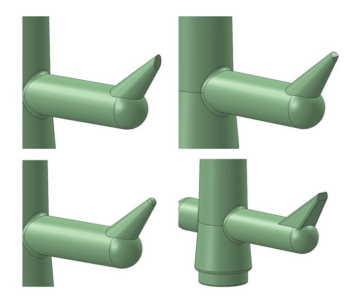
The four most common types of tunnel gate designs are (r-l) eliptical gate, D-gate, ball-gate and chisel gate.
An angled, conically shaped tunnel gate, also known as a subgate or submarine gate, is one of the best—and worst—types of gating methods. One of the reasons it’s the best is because a tunnel gate automatically separates or degates from the part when either the mold opens or when the parts and runner are ejected. This reduces labor—often from the equivalent of one operator down to just a quarter of an operator. And those savings add up fast. Another advantageous feature is their ability to be machined at almost any angle. This is very convenient when you want to gate into a location that would be inaccessible with other gate types, such as in the thickest section of the part.


There are various types of tunnel-gate designs. The four most common are:
- Full conical gate, which leaves an elliptical gate mark;
- Truncated cone or D-gate, which leaves a “D”-shaped gate mark;
- Spherical or ball-nosed gate, which leaves a perfectly round gate mark;
- Chisel gate, also called a flare gate, which leaves a rectangular gate mark.
All four have a knife-edge section of steel on the side nearest the parting line. That’s the edge that does the shearing. But the D-gate and ball-gate also have a knife edge on the opposing side. Those edges can wear out quickly during injection, especially if the material is filled or abrasive.
Common Problems
Tunnel gates have a bad reputation for freezing off too early, not being able to fill or pack out a part, or generating excessive shear. Those reported problems are almost always due to the tunnel gate being undersized. It’s common practice to make the depth of a standard edge gate 60% to 70% of the part’s wall thickness, and the width of the edge gate is typically twice the depth. The width affects the length of material flow, while the depth affects the ability to pack out the parts.
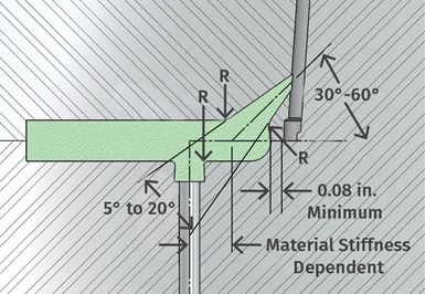
Typical tunnel-gate dimensions.
Avoid tunnel gating into a part that has a large taper.
Let’s say you have a part with 0.080-in. wall thickness. You might design an edge gate that is 0.050 in. deep by 0.100 in. wide. The flow area for this gate is therefore 0.0050 in.2. If you wanted to use a tunnel gate instead, you would probably use the same 0.050 in. as the “diameter,” because you assume that the same rule of thumb as an edge gate applies: 60% to 70% of the wall thickness.
And that’s where the error occurs.
For these two gate styles to have an equivalent flow area, you have to do the math. The flow area of an elliptical tunnel gate is equal to:
- (Pi X Height)/2 X Width/2, or
- (Pi X Height X Width)/4
If the tunnel gate in this example were on a 45° angle, the height (major diameter) of the ellipse would be 0.096 in. and the width (minor diameter minus the size the tool maker measures with a gage pin), would be 0.067 in.—not 0.050 in. If you used the 0.050-in. “diameter,” the flow area would only be 0.0028 in.2, almost half of the presumed “equivalent” edge gate. The interesting thing is that when these two gate types are designed with equivalent flow areas, the edge gate is the one that has less of a chance to pack out the parts, because it is shallower.
Some people think tunnel-gate orifices should be kept as small as possible so as not to increase the gate-seal time. That’s nonsense. Would you make an edge gate as small as possible for the same reason? What does it matter if the gate-seal time has to be increased? The parts are still solidifying, so the time required to cool the parts doesn't change. The worst-case scenario is you have get the screw back a little faster to maintain the cycle time.
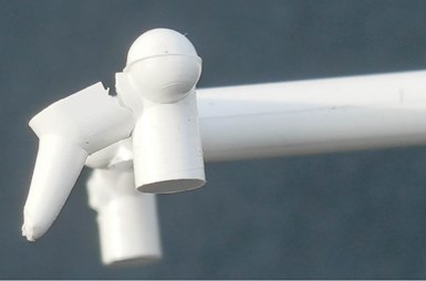
Other people think the base of a tunnel gate should never be larger than the diameter or width of the runner. That’s just total nonsense and should not even be considered when designing a mold. I have seen dozens and dozens of molds where the base of the tunnel gate was considerably larger than the runner—and they worked great. In fact, I often prefer a tunnel gate larger than the runner. There’s a larger mass that stays hotter longer and is more flexible. The material flow is less restrictive. And such gates are less prone to sticking in their bore.
There is no reason the base of a tunnel gate can’t be larger than the runner it connects with.
The height of a tunnel-gate vestige is predominantly a function of the angle of the part it is gated into.
Tunnel gates also get a bad reputation for leaving a high gate vestige, especially when the size of the gate is large. That’s partly nonsense. While the size of the gate usually affects the size of the vestige, the predominant controlling factor on how “clean” or how high a vestige you get is based on the angle of the wall it’s gated into. Tunnel gates typically don’t break away from the part. They are sheared off. The edge of the hole in the steel that is closest to the parting line does the shearing.
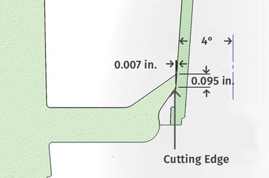
There are exceptions to this rule, such as if the material is highly flexible, the mold design has some flaws, or if there is some type of two-stage ejection system. Using the previous example, if the tunnel gate was gated into a part with 4° of taper on the side, you can expect to get a gate-vestige height of 0.007 in. Draft angles are more commonly down around 1°, which would make the vestige height just 0.001 in. Where you get into trouble is when you gate into a part with a large taper, or almost any radius. In these cases, the gate-vestige height can be fairly large. As the gate wears and needs to be sharpened, the size of the vestige gets even higher. Always try to avoid tunnel gating into a part that has a large taper, or into a radius.
Design Considerations
The length of a tunnel gate can be very short or very long. Shorter tunnel gates can often be machined at shallow angles, whereas longer tunnel gates require larger angles for easier removal. Keep in mind, longer gates start out farther away from the cavity, which makes for a stronger mold. Gates that have a shallow angle have to be machined close to the cavity wall. Since the injection pressure at the gate is extremely high, it is often the first place to flash. Using a separate gate insert for short tunnel gates is always a good idea. It will save you from having to do a lot of welding down the road.
Using a separate gate insert for short tunnel gates is always a good idea.
Tunnel gates also get a bad rap for being the cause of “jetting.” That’s usually nonsense. No matter what type of gate you have—edge, tunnel, cashew, fan, pinpoint, even hot-runner—unless the material is crawling into the cavity, they all jet to some degree until they hit an obstruction. The most common obstruction is the wall opposite the gate.
A small gate does increase the chance of jetting. And because tunnel gates are frequently undersized, a 0.030-in. gate will jet more into a 0.100-in.-wide cavity than a 0.060-in. gate will. There’s more room for the small stream of material flowing through the gate to snake around between the cavity walls. The distance between the gate and the first obstruction usually determines whether you are going to jet or not.
The reason I say tunnel-gate jetting is usually nonsense is because it depends on the angle of the tunnel gate. The angle of a tunnel gate’s center line usually ranges from 30° to 50° from the parting line, but I’ve seen that angle as low as 20° and as high as 60°. The higher the angle, the greater the chance of jetting. Instead of the material slamming into the opposing core right away, it’s shooting up into the open void. But material type, injection velocity, mold temperature, and a dozen other factors contribute to a jetting problem—not just the gate type.
In fact, I’ve seen a giant edge gate as large as 3/4 in. wide by 1/4 in. deep, jet into a wide-open cavity. As the tool designer, think about the potential for jetting and what you can change to minimize the risk. Sometimes you have to compromise between a large angle that may cause jetting, and a shallow angle that weakens the mold.
Regardless of the length, angle, or type of tunnel gate you chose, the bore must be polished—in draw. The exception to this rule is if the material is soft or elastomeric. Those materials release better with a matte finish. I also recommend all tunnel gates be machined by EDM, especially in multi-cavity molds. Since tunnel gates are often used on small parts, the gates are usually small. If the orifice size of the gates are not within 0.001 or 0.002 in. of each other, the part dimensions could vary.
In this business, it’s always helpful to think in terms of percentages. Let’s say one gate has a 0.030-in. diam., and another gate has 0.027-in. diam. That tiny 0.003 in. just choked off over 20% of the flow area. That particular cavity may have sink or voids because the gate froze off too early—all because of the thickness of a sheet of paper.
For shallow parts, stepping the parting line will allow you to use a larger tunnel-gate angle.
D-gates and chisel gates are much better than elliptical gates for gating into shallow parts. While I don’t recommend it, a chisel gate can also be machined to form a type of rectangular D-gate. But if you have concerns about the shallow angle required to gate into a shallow part, which can cause the gate to break off, you might be able to shift the parting line at the gate location to allow for a steeper angle.
When a tunnel gate is machined into the stationary side of the mold, some mechanical means is required to pull it out of its bore. Typically, a shortened ejector pin with an undercut or reverse taper is used for two-plate molds, and a sucker pin is used for stripper-plate molds. When the tunnel gate is machined into the moving side of the mold, some mechanical means is also required to pull it out of its bore. Again, a shortened ejector pin is typically used, but without the reverse angle.
Regardless of on which side of the mold the tunnel gate is installed, the distance between the ejector pin and the tunnel gate is critical, as well as the length of the boss formed by the shortened ejector pin. If the pin is too close, the tunnel gate cannot flex. If it’s too far away, it flexes excessively.
Either condition can cause a problem. Every mold design is different, as is every type of molding material. There are no carved-in-stone rules on where to locate these ejector pins. It all depends on the rigidity of the tunnel gate and runner when the mold begins to open. The more rigid they are, the farther away the ejector pin needs to be.
Plan on things going wrong, and have an option in mind to overcome the problem in case it does.
When tunnel gating into the stationary side of the mold, the boss formed by the shortened ejector pin does not have to be very long—typically only about the diameter of the runner. But when tunnel gating into the moving half of the mold, the boss must be at least the same length as the tunnel gate—not the depth of the gate, but its hypotenuse.
Sometimes it requires extremely long bosses to overcome tunnel-gate ejection problems, such as when the ejector pin is too far away from the tunnel gates.
One of the best lessons I was ever taught was to plan on things going wrong, and to have an option in mind to overcome the problem in case it does. When it comes to tunnel gates, rule number one is to leave a lot of bearing surface on the runner ejector pins. If you need to increase the length of the boss, but the pin is relieved, now yous have to install a stationary sleeve.
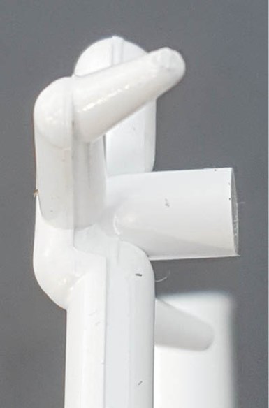
Puller ribs were added to a parabolic runner to detach a tunnel gate from the moving side during the mold-opening stroke.
I once had a mold where I wanted a tunnel gate that was machined into the moving side of the tool to detach from the part during the mold-opening stroke. Instead of incorporating an expensive two-stage ejection system, a parabolic runner was machined into the stationary side of the mold. The end of the runner had undercut or “puller” ribs with a slight angle machined into the side of the runner. As the mold opened, the runner flexed at the same time the ribs pulled the tunnel gate out of its bore. As the mold continued to open, the undercut ribs disengaged from the stationary side. A center sprue puller retained the runner, so that it could be ejected on the moving side when the mold was fully open.
Add a generous radius at all sharp intersections to prevent tunnel gates and runners from breaking.
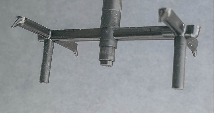
Just like any other type of gate, tunnel gates should be fed from a runner that has an overflow, or cold, well to prevent the gate from becoming blocked or unwanted material from entering the cavity. And just like any other gate, tunnel gates should have generous radii where the gate intersects the runner and where the runner intersects the ejector pin. If the material is brittle, there is a good chance it will break off in one of those two locations. Instead of using one shortened ejector pin per tunnel gate, I like to use two shortened ejector pins mounted equidistant from the gate. It costs a little more, but I have had great success with this design.
Using two ejector pins equidistant from a tunnel gate helps reduce the possibility of the gate breaking off.
Gate Flaking
Now let’s discuss gate flaking, or as I call them, mold killers. To repair an injection mold that has been damaged by flaking, you must grind the parting line to remove the hobbed surfaces and refit any shutoffs. But now the overall height of the part is shorter and possibly out of specification. Additionally, the wall thickness at the top of the part is now thinner, which can lead to a “racetrack” or a “back-fill” condition. To eliminate that condition, you must grind off the top of the cores, but you are still left with a shorter part. To get back into specification, you also must machine the cavities deeper and re-polish. Therefore, to correctly repair the damage caused by flaking tunnel gates, you almost have to rebuild the entire mold. That’s why I call them mold killers. So how do you prevent flaking?
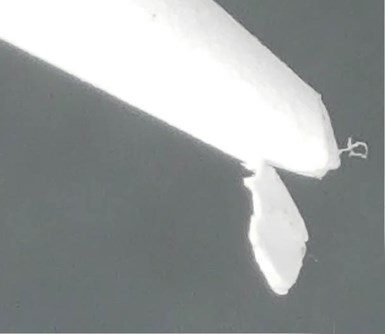
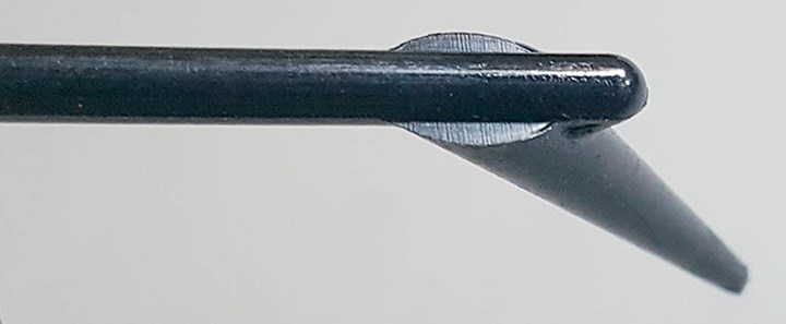
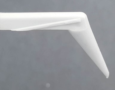
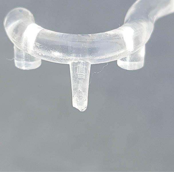
Tunnel-gate flakes are created by the tip of the gate breaking off at the split second before it exits its bore.
To understand how to prevent flakes, you have to first understand what causes them. The photo below left shows a small flake at the tip of an elliptical tunnel gate. As the tunnel gate is withdrawn from its bore, it flexes. This flexing “spring loads” the tunnel gate, which will try to spring back to its original shape when it’s fully out of its bore. The flake is created at the split second before the tunnel gate is withdrawn. The spring force is greater than the strength of a small segment of rigid plastic at the tip of the tunnel gate, which causes it to fracture. Sometimes it’s held onto the tunnel gate by a whisker. Sometimes it falls down into the chute. But thanks to that devil, static electricity, it usually adheres to the face of the parting line.
Elliptical tunnel gates are the biggest culprits for flaking, especially if the gate is long and the angle from the parting line is over 45°. That’s when the major diameter of the ellipse is the largest and the structural integrity of the tip is the weakest. D-gates are pretty good at not flaking. But chisel gates are the best because they are wide, and their structural integrity is considerably stronger. Chisel gates also leave the least amount of gate vestige because they are the shallowest of any tunnel-gate type—assuming they have equivalent flow areas.
But before you make your selection of the type of tunnel gate to use, check the material supplier’s design manual. Some types of materials demand a particular gate, and it may not be one of the four described in this column.
ABOUT THE AUTHOR: Jim Fattori is a third-generation injection molder with more than 40 years of molding experience. He is the founder of Injection Mold Consulting LLC. Contact: jim@injectionmoldconsulting.com; injectionmoldconsulting.com.
Related Content

How to Stop Flash
Flashing of a part can occur for several reasons—from variations in the process or material to tooling trouble.
Read More
The Effects of Temperature
The polymers we work with follow the same principles as the body: the hotter the environment becomes, the less performance we can expect.
Read More
The Importance of Melt & Mold Temperature
Molders should realize how significantly process conditions can influence the final properties of the part.
Read More
Understanding Strain-Rate Sensitivity In Polymers
Material behavior is fundamentally determined by the equivalence of time and temperature. But that principle tends to be lost on processors and designers. Here’s some guidance.
Read MoreRead Next

Advanced Recycling: Beyond Pyrolysis
Consumer-product brand owners increasingly see advanced chemical recycling as a necessary complement to mechanical recycling if they are to meet ambitious goals for a circular economy in the next decade. Dozens of technology providers are developing new technologies to overcome the limitations of existing pyrolysis methods and to commercialize various alternative approaches to chemical recycling of plastics.
Read More
Why (and What) You Need to Dry
Other than polyolefins, almost every other polymer exhibits some level of polarity and therefore can absorb a certain amount of moisture from the atmosphere. Here’s a look at some of these materials, and what needs to be done to dry them.
Read More
How Polymer Melts in Single-Screw Extruders
Understanding how polymer melts in a single-screw extruder could help you optimize your screw design to eliminate defect-causing solid polymer fragments.
Read More