Temperature control units are relatively simple in their design and operation, but the impact they have on industrial processes can be significant. To better understand this, it is important to review:
- The components of construction
- How the units operate
- Factors to consider when selecting a design for a specific application
A temperature control unit, or TCU as it is commonly known, has two major components: the pump and the heater. Both are managed by a programmable logic controller (PLC).
During operation, a temperature setpoint is input into the controller. The pump continually circulates a fluid — most commonly water — from the TCU to the process and then back to the TCU. This is referred to as the temperature control loop or process loop. While the fluid is circulated through this loop, the controller will monitor input from a temperature sensor on the TCU’s return line.
If the fluid is returning to the TCU lower than the setpoint, this means energy is being transferred from the fluid into the process. Therefore, the TCU is heating the system. The controller will activate the heater in the TCU to add more energy to the fluid. Conversely, if the fluid is returning to the TCU warmer than the setpoint, this means energy is being transferred from the process into the fluid. In this case, the TCU is cooling the system. The controller reacts to this situation by actuating the cooling valve.
Indirect or Direct Cooling Operation
The TCU does not generate the cooling itself. Instead, it utilizes a cooling source to lower the process loop’s fluid temperature. Common cooling sources are a chiller system, a cooling tower system or city water.
Two configurations are possible for the cooling operation: direct and indirect. The name refers to how the cooling source fluid interacts with the process loop fluid.
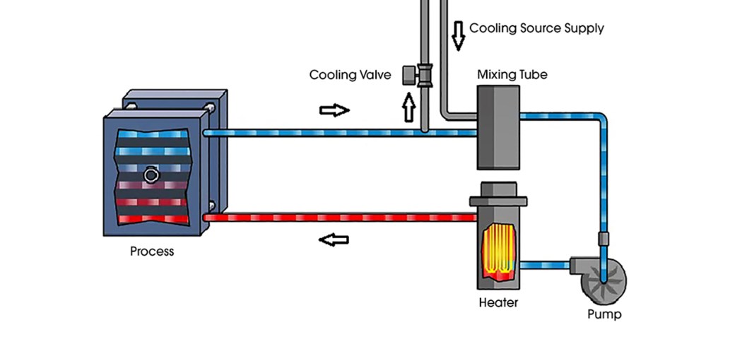
For direct-injection cooling, when the cooling valve is opened, it allows the warm fluid from the process loop to escape from the system. This warm fluid can go directly to a drain or into a return line going back to a cooling source such as a chiller.
The cooling source supply replaces the volume that released from the process loop. The cooler fluid is mixed directly into the warmer fluid of the process loop, which reduces the temperature of the system, achieving the desired cooling.

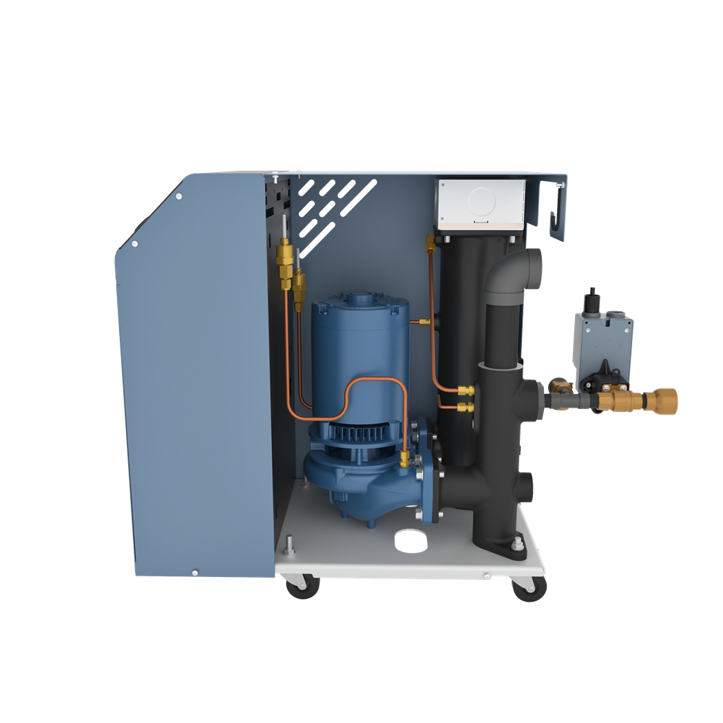
This typical TCU shows the pump and heater tube.
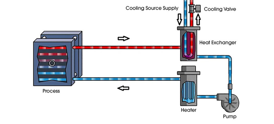
Indirect designs still use a cooling valve, but the process loop’s fluid is isolated from the cooling source fluid with a heat exchanger. The cooling valve controls the flow of the cooling source fluid through the heat exchanger. The warmer fluid transfers energy into the cooling source fluid, thus achieving the required cooling.
There are pros and cons to each cooling style. Direct injection mixes the two fluids, so contamination is a concern. The energy transfer rate is not limited by a physical heat exchanger, however. Indirect cooling maintains separation of the fluids, but it is limited by the capacity of the heat exchanger. There also are implications for the maximum setpoint of the system because of pressurization requirements that make high temperatures possible.

Indirect cooling maintains separation of the fluids, but this method has a more limited flow based on the capacity of the heat exchanger.


