
Extrusion: How Hopper Crammers Can Help Feeding
A crammer can assist the flow of certain polymers into the extruder. But the design is not universal and very material dependent. Here’s what you need to know.
.jpg;width=70;height=70;mode=crop;format=webp)
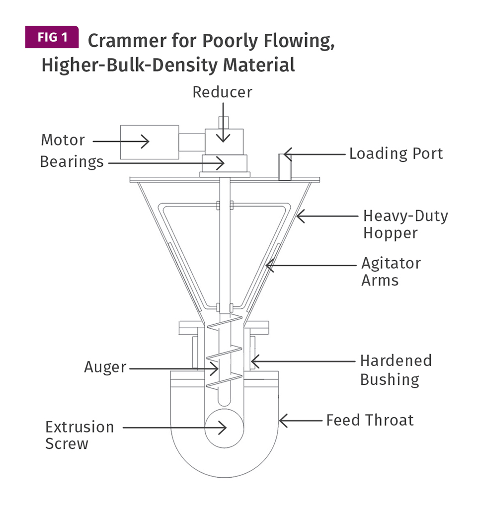
Crammer for poorly flowing, higher-bulk-density materials.
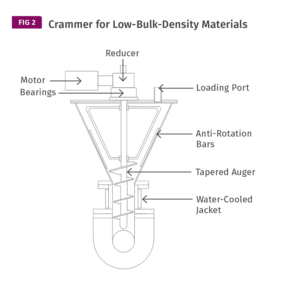
This crammer is for low-bulk-density materials like film or foam. Note that the auger tapers outward to conform to the hopper taper. This lets it get a bigger “bite” of the material and give it some preliminary compaction as it enters the auger.


There are some polymers that are not free-flowing enough for conventional hopper-fed extruders even with optimal feed-throat and hopper designs. Then there are materials that have such a low bulk density that they significantly reduce the output of the extruder. And some materials have both issues. One solution is to add a hopper crammer.
Although it looks like a relatively simple device, designing a hopper crammer requires a tricky combination of experience and engineering. There is no universal crammer design; it depends heavily on the characteristics of the material being crammed. So it’s important to understand the polymer particles’ characteristics for flow, packing, bridging, and bulk density to determine how to design the crammer. Most of this analysis is done using small material samples along with reviewing the current feeding performance of the extruder.


The goal of a properly designed crammer is to deliver material to the extruder screw uniformly without generating much temperature rise or excessive pressure.
The free-flowing characteristics can usually be estimated by the angle of repose and by passing the material through a large funnel. Packing can be estimated by putting a cup-full into a plastic bag and squeezing it. Bridging is related to both the angle of repose and the packing. Bulk density can be measured by simply filling a calibrated container and weighing it. With that data you can size the hopper for adequate capacity to service the extruder’s desired output and start to develop the crammer design.
To design the auger there are helpful tables of tubular screw-conveyor data on the internet that take into account similar material characteristics. But they do not provide for compaction of very low-bulk-density materials. That is always an unknown and is based almost entirely on experience. Kase Conveyors has a handy screw guide on its website that I have found useful. It estimates the screw speed and horsepower needed How Hopper Crammers Can Help Feeding to feed some materials, allowing you to specify the auger and drive system. Naturally some margin for error must be allowed, as there are no exact formulas and no exact measurements of the materials’ characteristics. Since the auger is operating vertically downward, the rate typically meets or exceeds the rates noted for tubular screw conveyors that are based on no elevation change.
Most crammer augers use a standard flight pitch, as that usually provides the best overall results, unless there is actual data available on other helix angles for that particular material. Figure 1 is typical of a crammer for a poorly flowing but higher bulk-density material, where bridging or tunneling of the material is problematic. Figure 2 is typical of a crammer for low-bulk-density materials like film or foam. The difference is that the auger in Fig. 2 tapers outward to conform to the hopper taper. This lets it get a bigger “bite” of the low-bulk-density material and give it some preliminary compaction as it enters the auger.
The crammer hopper must be of much heavier construction than a conventional hopper because it has to resist the torque of the screw rotation as well as the upward thrust of the screw. A 6-in. crammer auger that generates only 200 psi of polymer pressure will generate more 5500 lb of upward thrust force. Consequently, you’ll need a thrust bearing with radial bearings for alignment to isolate the reducer/motor from the thrust and support the screw shaft—just like a thrust assembly on an extruder.
Get more insights on Extrusion from our expert authors: Extrusion Know How
The hopper cover or lid also must be very strong to resist bending from the upward screw thrust and to support the weight of the reducer/drive. At the entrance to the feed throat, a hardened or bimetallic bushing is usually used to reduce wear from the auger rotation because it has little centering support due to the long shaft and has extra clearance to prevent frictional melt formation. As a result, it sort of “bangs around” in the bushing, causing wear. The bushing should be in a water-cooled jacket to further prevent any melt from forming between the barrel wall and the screw flights, even with the added clearance. Any melt formation on the screw will completely stop the feeding and is difficult to clean—usually the entire crammer must be completely disassembled.
In addition to estimating the torque required for screw rotation, there is added torque required for rotation of the agitator arms. This is truly a guess based on the cross section of the agitator bars and the material characteristics. The angle of repose and the packing tendency govern that estimate. For the agitator bars to move through the material and prevent bridging, the material must not slip excessively on the hopper wall. That often requires bars to be mounted on the inner hopper wall to resist rotation of the entire mass in the hopper, just like in a grooved-barrel extruder.
The crammer hopper must be of much heavier construction than a conventional hopper because it has to resist the torque of the screw rotation as well as the upward thrust of the screw.
The goal of a properly designed crammer is to deliver material to the extruder screw uniformly without generating much temperature rise or excessive pressure. Over-cramming can bring on a lot of unintended consequences. Even with a very well-designed crammer and extruder screw there is a tendency for operators to over-drive it to boost output above the screw’s optimal rate. An over-driven crammer can cause surging as it “over-stuffs” the feed section, leading to inconsistent output, high screw/barrel wear, drive overload, poor melt quality, feed-throat melting, and even extruder reducer bearing failure due to a high side load on the bearings. Designs for low-bulk-density materials are generally more problematic than those for materials with poor flow.
Some extrusion operations cannot process effectively without use of a crammer or other device to assist polymer flow into the extruder. However, there are enough negative aspects to using a crammer that it’s advisable to be certain that changes in hopper, feed-throat, and screw design cannot solve the feeding issues before installing a crammer.
ABOUT THE AUTHOR: Jim Frankland is a mechanical engineer who has been involved in all types of extrusion processing for more than 40 years. He is now president of Frankland Plastics Consulting, LLC. Contact jim.frankland@comcast.net or (724) 651-9196.


Related Content

Moving Beyond the Relative Viscosity Curve — New Method To Find Optimum Plastic Flow Rates: Part 2
Explore the use of the injection unit velocity capability, which determines a machine’s injection speed linearity to find optimum flow rates, and proposes a second method.
Read More
Bringing Order to the Chaotic Debate of Turbulent Flow in Injection Molding
Is turbulent flow required for all cooling channels to optimize the cooling process in injection molding? It depends. Author reviews the Reynolds number, advanced cooling technologies, simulation’s potential role and more.
Read More
A Systematic Approach to Process Development
The path to a no-baby-sitting injection molding process is paved with data and can be found by following certain steps.
Read More
How To Identify Resin Degradation in Single-Screw Extruders
Degradation can occur in many single-screw extrusion operations, and typically occurs due to minor design flaws in the screw. Here is how to track it down.
Read MoreRead Next

People 4.0 – How to Get Buy-In from Your Staff for Industry 4.0 Systems
Implementing a production monitoring system as the foundation of a ‘smart factory’ is about integrating people with new technology as much as it is about integrating machines and computers. Here are tips from a company that has gone through the process.
Read More
For PLASTICS' CEO Seaholm, NPE to Shine Light on Sustainability Successes
With advocacy, communication and sustainability as three main pillars, Seaholm leads a trade association to NPE that ‘is more active today than we have ever been.’
Read More
Beyond Prototypes: 8 Ways the Plastics Industry Is Using 3D Printing
Plastics processors are finding applications for 3D printing around the plant and across the supply chain. Here are 8 examples to look for at NPE2024.
Read More


