
How to Form a Hole with a Core Pin: Part 2
Prevent wear, flash, and mold damage with these design methods.


Last month I discussed several basic methods of forming a through hole in a molded part. This month I will go into more detail and provide more variations that you may consider. You might also consider combining various features from several of these methods to suit your particular application.
Figure 1 depicts six of the more common methods for creating a through hole in a molded part. All of them use a core pin. While Fig. 1 shows core pins mounted in a B-Plate, most of these methods can be applied to core pins mounted in the A-Plate, an ejector sleeve, or even a cam. Additionally, while the methods discussed here apply to cylindrical core pins, they can also be incorporated into a variety of shapes with the same intent and purpose—for example, forming a keyhole in a molded part.


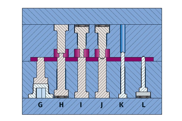
FIG 1 Various methods to form a through hole (G-L).
Method G: This depicts a core pin designed for a hole diameter that is extremely critical. The pin is slightly larger in diameter, and then stepped to the desired size for the hole in the part. If the hole in the molded part ends up being too large for the established process parameters, you can grind the steel-safe pin slightly smaller. If the hole in the molded part ends up being too small, the pin can be replaced without having to increase the diameter of the through hole.
This method works well for both blind and through holes in a part. The core pin retainer holding the pin in place is an inexpensive and effective method you might consider for non-laminated B-Series mold bases, stripper plates, and other designs where there is no retainer plate.
Method H: Here, two opposing core pins butt off against each other. Using through-hardened core pins is essential for this type of application. Spring loading one of the pins will greatly prolong the longevity of both pins. I wonder how many of you realized that the drawing is incorrect. (Yes, it was a test.) Since the core pin on the core side of the mold is spring loaded and the hole is counterbored, the spring-loaded pin will try to push the molded part off the core—possibly causing it to stick in the cavity.
When a hole in a part is fairly long and the hole diameter fairly small, it is common to use two opposing core pins to reduce the length. If the two pins have the same diameter, one of them should be intentionally a little larger than the desired hole diameter. In the event one of the pins deflects due to the flow of molten material, a screw, pin, or other item can pass through the hole unobstructed.
Method I: This is basically a mirror image of Method H. However, in this case the spring-loaded pin on the cavity side helps prevent the part from sticking in the cavity. It doesn’t matter if the section with the reduced diameter is made with the pin in the cavity or the core. The part design will dictate which configuration is preferable.
Method J: Method J is the same as Method I, except that the faces of the core pins are interlocked. There are various designs for interlocking two mating pins. Ideally, the one you use should allow any debris to fall freely out of the female portion of the interlock every time the mold opens. Or you should provide space between the male and female interlocks to retain some debris.
Notice how the interlock does not extend all the way to the edge of the pin. There is a small ledge, or flat portion on the face of the pin with the male interlock. This is done to prevent side flash. Interlock two mating pins whenever the concentricity is critical, the height of the smaller-diameter pin is extremely long, or there is a high probability of the flow of plastic material bending the pin.
Interlocks should allow debris to fall freely out of the female side.
Method K: This depicts a small-diameter core pin. The through hole for small pins should start from the parting line of the mold because when you machine a hole from the back of the cavity or core insert, you run the risk of the drill or end mill “drifting.” This is also why the through hole for small core pins should be relieved.
Reamers, laps and hones can help repair a hole that is curved, or shaped like a banana, but they can’t straighten out a hole if it is not perpendicular to the parting line. That is when either jig grinding, or high-speed milling is required. Small core pins have a high risk of bending. They should be piloted into the opposing mold component by whatever method you prefer. (Also see last month’s article for various methods of piloting.)
Method L: This is an alternative to Method K. The pin enters the cavity only by the amount of the interlock. As in Method J, a small flat is on the face of the pin to prevent side flash. The pin is spring-loaded to compensate for any variation in height or injection pressure. Since the pin diameter is small, a hardened spacer is used between the back of the pin and the top of the stacked Bellville springs. This allows the use of springs with sufficient force.
Align Precisely
No matter which method you use to form a hole in a molded part, it is extremely important to have precise alignment between the cavity plate and the core plate. Conical interlocks may be acceptable when a pin butts off against a flat surface. They are also acceptable for pins that are interlocked, as long as the angle on the pin’s interlock is greater than the angle on the conical interlock. For piloted core pins that enter a cavity, straight-sided interlocks are required with an engagement length longer than the engagement length of the core pin in the cavity.
Proper alignment is the key to a mold’s longevity.
How Much of a Taper?
As the molten plastic cools, it shrinks onto the core pins. Effectively, the pins are an immovable cooling fixture. Therefore, core pins, like the cores themselves, typically require more draft or taper than the cavity does. Materials with higher shrink rates will apply more holding force than materials with a low shrink rate—and therefore require more taper. The type of material can also dictate the amount of taper required, as well as the core pins’ surface finish. If in doubt, you should contact the material supplier for guidance. Occasionally, you may want to add negative taper so that the core pin functions as a puller to pull a feature out of the cavity.
Add Clearance
When installing core pins in a core insert or B-plate, it is common to add a little clearance between the pin and the hole. Obviously, the clearance needs to be less than the vent depth for the plastic material to be molded. The advantage of this small amount of clearance is to allow the core pin to float slightly due to inevitable misalignment. It also acts as a stationary vent for trapped gasses and can improve the strength of the weld or meld line of the plastic as it flows around the pin. Note: If weld line strength is a primary concern, especially for load bearing items such as threaded inserts, it might be best to use a very short and pointed core pin. This will form a locating position for a secondary drilling operation.
Contrary to having a slight clearance around core pins, if you need to maximize the amount of heat transferred from the exposed portion of the pin to the insert that retains it, then the pin should have a light press fit—not a slip or slight clearance fit.
Consider Thermal Expansion
A mold may be perfectly fitted on the bench, but it will start to expand after a few minutes of exposure to hot plastic or plates that are heated with hot water or oil. There is also the common and more concerning scenario where the processor intentionally uses a hotter temperature on the A-plate to prevent parts from sticking in the cavities. The larger the mold, the more this can become an issue. In a case like this, consideration should be given to interlocking the individual cavities and cores, as opposed to interlocking just the A and B plates. The cavity or core should be allowed to “float” a little when they are individually interlocked, otherwise, the interlocks can end up “fighting” each other.
If the cavities or cores are cut in a solid, as opposed to individual inserts, there are very few options to counteract thermal expansion issues between the mold halves. One option is to calculate the amount of thermal expansion and install a bushing. The bore of the bushing can be offset from the centerline by the amount of thermal expansion.
Pin Removal Tips
Core pins are typically removed by tapping on the face of the pin with a piece of brass, aluminum, wood, or dead-blow hammer. But core pins are often too thin, small, or fragile to be removed by this method. Therefore, a suitable method of pulling the core pin out from the back of the plate is required. A tapped hole in the head of the pin works well for pulling out core pins. Especially if the mold had a water leak and the pin is rusted tight in its hole.
Deflection
Mold designers should account for the length-to-diameter ratio, or L/D. This ratio refers to the unsupported length of the exposed core pin divided by its diameter, as shown in Fig. 2. The higher the L/D value, the more the core pin is susceptible to deflecting.
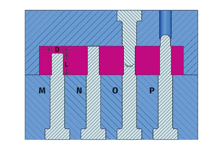
FIG 2 Various core-pin configurations.
Accounting for Core-Pin L/D Ratio
While researching this topic, I found several rules of thumbs from various sources. As the diameter of a core pin increases, so does its maximum L/D ratio. A core pin that forms a blind hole has a much lower L/D ratio then a core pin that forms a through hole. The design, or configuration, of how a core pin is retained also has a significant affect o the maximum L/D ratio.
I combined all this information and did some interpolating to derive a more user-friendly chart, as shown. Keep in mind, these values are strictly rules of thumb. There is only one way to get a more accurate prediction on whether a core pin (or even a core) will deflect, and that is with a flow analysis. A flow analysis can predict the velocity and viscosity of the molten material at the precise time it impinges against the core pin.
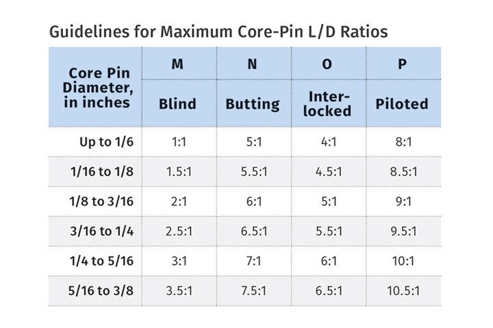
If you experience a problem with core-pin deflection, it can often be overcome by profiling the injection velocity. Reduce the velocity just before the material hits the pin, and then speed it back up to the desired velocity a short distance beyond the pin. This can increase the effective L/D ratio by two to four points.
The L/D ratio guidelines in the chart are based on the material flowing from one direction. When a part design has an extremely large L/D ratio, for example a pen barrel or a syringe, two or more gates are typically incorporated. Multiple opposing gates can often allow L/D ratios as high as 15:1 to 20:1.
Designing an injection mold to work well and last a long time with minimal repair costs and downtime is not difficult if you pay attention to the details.
ABOUT THE AUTHOR: Jim Fattori is a third-generation molder with more than 40 years of experience in engineering and project management for custom and captive molders. He is the founder of Injection Mold Consulting LLC in Pennsylvania. Contact: jim@injectionmoldconsulting.com;
injectionmoldconsulting.com


Related Content

Understanding Strain-Rate Sensitivity In Polymers
Material behavior is fundamentally determined by the equivalence of time and temperature. But that principle tends to be lost on processors and designers. Here’s some guidance.
Read More
PBT and PET Polyester: The Difference Crystallinity Makes
To properly understand the differences in performance between PET and PBT we need to compare apples to apples—the semi-crystalline forms of each polymer.
Read More
How to Get Rid of Bubbles in Injection Molding
First find out if they are the result of trapped gas or a vacuum void. Then follow these steps to get rid of them.
Read More
How Much L/D Do You Really Need?
Just like selecting the extruder size and drive combination, the L/D should be carefully evaluated.
Read MoreRead Next

How to Form a Hole with a Core Pin: Part 1
Prevent wear, flash, and mold damage with these design tips.
Read More
What You Need to Know About Blade Ejectors: Part 1
Follow these guidelines to prevent premature wear, flash and galling.
Read More
80 Questions Moldmakers Should Ask Themselves … and Their Customers
If you’re a molder or brand owner/OEM, be ready to supply the answers before the program is launched.
Read More