
How to Select the Right Tooling for Pipe Extrusion
In pipe extrusion, selecting or building a complementary set of tooling often poses challenges due to a range of qualitative factors. Here’s some guidance to help you out.


Selecting the right extruder and downstream equipment are two prerequisites for the successful installation and operation of a new pipe extrusion line. However, there’s a third, vitally important factor: the right tooling.
Consisting of the pipe die, calibration/sizing tooling, cooling system and downstream supports, extrusion tooling makes all the difference between a pipe production line that should work, and one that works optimally. Pipe tooling is to a pipe production what an assembly line is to the quality of a car or appliance: It’s the element that receives the essential parts of the product (for example, heated and extruded material flows, colors, markings and more) and assembles, aligns and shapes them into a finished product.


With all other upstream and downstream equipment being equal, deviations in tooling specification, manufacturing or tolerances will result in measurable differences in the fit, finish and yield of your final pipe product, or in production failures and the need to retool.
Factors in Specifying, Selecting the Right Pipe Tooling
Many of the factors needed to specify optimal pipe tooling are the same ones required for selecting the extrusion line and downstream equipment. They are:
- Pipe dimensions and dimensional tolerances: When manufacturing involves standard pipe sizes (such as ASTM Sch 40, Schedule 80 PVC), dimensions and tolerances are clearly defined. Otherwise, for custom work, dimensions and tolerances (minimum and maximum) must be defined:
- Outside Diameter (OD)
- Wall thickness
- Concentricity
- Pipe composition (single vs. multilayer, single or multiple materials): The majority of pipe produced is standard single-layer, solid-wall PVC or HDPE. Both of these materials run through a single extruder, into a single pipe die (Figure 1) and down the line.
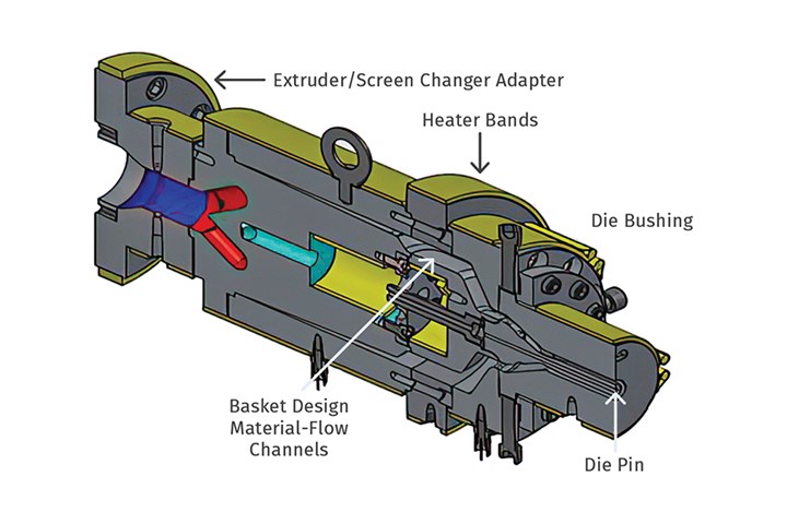
FIG 1 Cross section of a single-layer pipe head, showing how the melt from the extruder splits when it reaches the die pin and is then channeled into a series of flow paths that later merge to form the circumference of the extruded pipe. Photo Credit: Conair
However, some customers elect to run multilayer pipe using these materials. The most typical multilayer pipe consists of three layers, with a center layer of regrind delivered from one extruder that is sandwiched between two layers of virgin material delivered by another extruder, with all of the materials coming together in a multilayer pipe die (Figure 2). Other multilayer pipes may combine two or more materials, consisting of a base material layer with additional layer(s) of a different material with barrier properties.
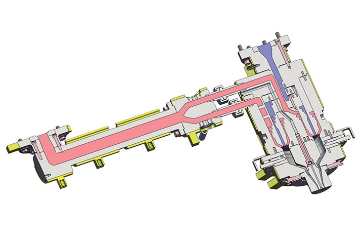
FIG 2 Multilayer pipe die. Photo Credit: Conair
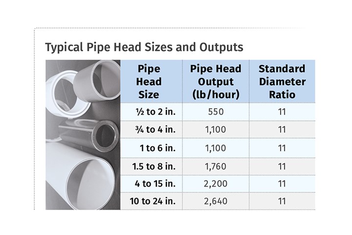
- Extruder capacity or line output requirements (size and lb/hr output): Specifying equipment and tooling requires that the customer provide an output size for the pipe (such as 3-inch Sch. 40) and/or a capacity/output target for the extruder (such as lb/hour). Then, the equipment supplier must help the customer balance the production goal against the available production space and capacity of the equipment. Said another way, the principal constraint on production is usually extruder capacity, especially in smaller size ranges. A processor who wants to run 2,000 lb/hour of 2-inch pipe isn’t going to be able to do it on a single line; based on extruder capacity for that size (see table), it’s probably going to require two lines.
- Pipe coding and marking requirements: To meet identification, traceability and retail distribution requirements, extrusion equipment specification must allow the processor to code and mark their pipe products. Typically, coding and marking requirements vary based on the pipe material composition. Some pipe materials are very easy to mark using an inline printing device, with PVC being a prime example. Other common pipe materials, such as PE so often used in pipe used to reline sewer or gas lines, can be very difficult to print consistently.
When inline printing is not possible, it becomes necessary to use a multilayer extruder, with an additional small extruder that embeds colored markings or stripe(s) into the surface of the extrudate before it enters the pipe head.
- Inline or downstream cooling requirements: Finally, there’s the matter of cooling the extruded pipe, which is critical to setting its shape, hardening its surfaces and enabling it to shrink down to its finished size. Typically, this involves passing the pipe through a vacuum-cooling tank or utilizing internal compressed air cooling, both of which are discussed below.
Key Factors in Pipe Heads and Selection
Pipe heads are typically designed to accommodate a range of pipe sizes and outputs. Some typical output ranges are listed in the accompanying table above, based on a standard dimension ratio (SDR) of 11, a very common SDR that means the pipe sidewall thickness is equal to 1/11th of the pipe diameter.
As the first major piece of tooling, the pipe head receives a flow of molten plastic from the extruder, then distributes that flow outward into a circular pattern that forms the shape of the pipe. A well-designed pipe head works with the extruder to move the plastic through the pipe die evenly, without generating excessive pressure that could begin to distort the pipe dimensions. There are several major factors involved in selecting the right pipe head:
Spider or spiderless/basket design: The first key variable in the pipe head is the internal configuration that holds the die pin inside the melt flow to form the inner diameter (ID) of the pipe. Pipe dies feature two basic designs, each of which offers extrusion challenges but can be optimized for particular types of material.
- A spider-type pipe head holds the die pin in the melt flow with thin metal legs, analogous to a wheel with a few very thin spokes. The issue with this design is that when the plastic flows over the spider legs, the flow has to split up and then “weld” back together as it moves up the die pin. If the edges of the flow do not weld together homogenously due to material characteristics, weak spots can occur, which, for pressure-bearing pipe, could cause performance concerns.
- The other main type of pipe head is a spiderless or “basket” design, which can be thought of as a solid wheel where material moves through many hollow internal spokes. This design channels the melt through a series of flow channels in the metal structure that holds the die pin, then merges the many flows together to form the pipe’s shape.
Spider-type pipe heads were developed first, with spiderless pipe heads evolving later to cope with different materials and pipe requirements. One key difference is in the heat tolerance of the materials you’re extruding. Generally, rigid PVC extrudes very smoothly through a spider-type pipe head. However, to extrude polyolefins like HDPE and PP, a basket design is preferred. The difference is in the polymer molecule — polyolefins have a more stable molecular structure, so they can tolerate the more restrictive basket flow channels, while PVC tends to degrade and burn when pushed through more restrictive die flow channels.
Land length: Land length refers to the length of the area of the pipe head where the pin and bushing run parallel to each other. Getting this length right is essential to stabilizing the melt as the pipe begins to form, prior to exiting the pipe die. Too little land length can cause the pipe shape to vary as it leaves the die, resulting in dimensional instability. But too much can create resistance (backpressure) which can restrict die output. A general guideline for producing HDPE pipe is a 30:1 ratio of land length to wall thickness.
Internal air cooling: Because of the mass of hot extrudate in a larger pipe size, external cooling alone is insufficient to cool and stabilize pipe dimensions when pipe exceeds 10 inches in diameter. So, an internal flow of cooling air, delivered through the die head, is used to carry away internal heat while providing positive pressure to maintain the ID of the pipe during vacuum sizing. The hot air flows through and out of the pipe as it moves further downstream. The practical effect of internal cooling is that it can save extrusion floor space by reducing the number or length of external cooling tanks required.
Factors in Calibration, Sizing and Cooling
Remember that tooling helps to assemble and transition the elements of the extrusion as they proceed down the line. One of the most visible and critical requirements of tooling is to manage the flow of “hot” pipe material as it exits the pipe head and then rapidly “draws down” to enter calibration tooling, which begins the sizing and cooling process.
Material Drawdown: “Drawdown” refers to the degree to which a “hot” pipe extrusion shrinks or “necks down” between the exit of the pipe head and the entrance of the sizing tooling, specifically the neck of the calibration sleeve on the vacuum cooling tank. To enable drawdown, the pin and bushing back in the pipe head are engineered to be larger than the nominal pipe size being produced. Ideally, the excess in size enables the melt flow to cool and shrink (drawdown) just enough to “seal” the circumference of the pipe as it enters the calibration sleeve — which is the first element of vacuum sizing tooling.
If the hot pipe exits the head being too small (not enough estimated drawdown), it won’t complete the tooling seal needed for vacuum sizing to optimize its dimensions during cooling. This will result in leakage of lubricating water from the neck of the calibration tool. If the pipe comes out too large (too much estimated drawdown), the melt will jam at the entrance of the sizing tool. Such jamming causes uneven stress in the molecular structure of the pipe and can result in reduced burst strength and other problems.
The degree of drawdown is substantial and material specific, so predicting and engineering extrusion tooling to get it right can be time-consuming. However, there are some general guidelines, based on experience: Drawdown on polyolefins generally ranges from 30% to40%, while PVC draws down 15-20%, for example. Watching material shrink so much in the few inches of open air between the pipe head outlet and the neck of the sizing tool really brings home the importance of getting drawdown right.
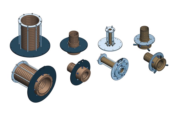
FIG 3 Placed at the entrance to a vacuum cooling tank, calibration sleeves receive the hot extrudate from the pipe die. All along the sleeve structure, openings or grooves in or between the sleeve segments admit spray cooling water to help stabilize the pipe surface as it passes through the tank. Photo Credit: Conair
Calibration tooling. As the hot pipe material draws down, it enters a calibration sleeve, which is mounted at the entrance of a vacuum cooling tank. The calibration sleeve (Figure 3) is expected to perform a range of vital tasks and therefore relies on a series of design elements:
- Correct adjusted internal diameter: The internal diameter of the calibration sleeve must be larger than the final pipe diameter because the melt continues to shrink as it cools.
- Sleeve Length. The sleeve must be long enough to stabilize and “set” the skin of the pipe outer diameter (OD). Typically, sleeve length is calculated based on a ratio involving line speed, with faster line speeds dictating longer sleeve length. If you get the length too long, the pipe will encounter frictional drag as it passes through.
- Entrance water lubrication. A flow of water, supplied by a cooling pump and a temperature-control unit in the vacuum sizing tank, circulates at the neck of the calibration sleeve to lubricate the pipe as it enters. Pulled inward by vacuum within the tank, the water forms a hydraulic seal between the edge of the sleeve and the pipe, indicating that drawdown and tool size are correct. Further down the sleeve, circulating water contacts and cools the surface of the pipe through slots or spaces along the surface of the sleeve.
- Sleeve material. Calibration sleeves are typically made of bronze, which strikes a balance between two essential qualities: durability and heat conductivity. By way of comparison, aluminum is an excellent conductor but lacks durability, while stainless steel offers superior durability but poor conductivity.
- “Metal-rich” design. Because there are so many factors at play in pipe sizing and cooling, extrusion professionals typically build vacuum calibration tooling “metal rich.” That is, they start by building initial tooling on the small side regarding OD, leaving plenty of extra metal available, especially when the job involves nonstandard pipe sizes. When multiple extrusion runs are required to optimize drawdown and sizing, a metal-rich approach enables continued honing of the calibration tooling to gradually enlarge the aperture until optimal fit and pipe sizing are achieved.
With so much going on within the calibration sleeve, one might wonder if the work of sizing the pipe is done in a single step with the calibration sleeve. That’s not so. Especially on fast-moving, high-output extrusion lines, the calibration sleeve only “sets the skin” on the outermost material or layer of the pipe, stabilizing it so the pipe can undergo subsequent cooling.
Vacuum tank tooling: Initial water cooling for pipe is provided in one or more vacuum cooling tanks (additional nonvacuum cooling tanks may also be required.) When vacuum is applied to the exterior of the hot pipe, airflow within the pipe exerts relative positive pressure to maintain the ID of the pipe.
Because of the mass of material in larger size pipes, pipes can take a long time to cool, shrink and harden to finished size. So, it is vital to have another set of properly adjusted tooling — pipe supports — within the vacuum cooling tank and other downstream tanks, when those are necessary. Pipe supports that are shaped to the pipe OD, acting as an extension of the sizing tool, must follow the sizer to maintain the OD of the pipe as the melt continues to cool. Often, the need for these supports is overlooked or treated as an afterthought in the design of an extrusion tooling package, but they’re vital.
Experience shows that solid supports, properly sized and formed of materials like UHMW PE (for good surface lubricity) offer a superior combination of stability and support within a cooling tank (Figure 4). Some might suggest using rollers within vacuum or cooling tanks, but rollers can move and shift due to the size and mass of the pipe, resulting in irregularities or flat spots on the pipe surface.
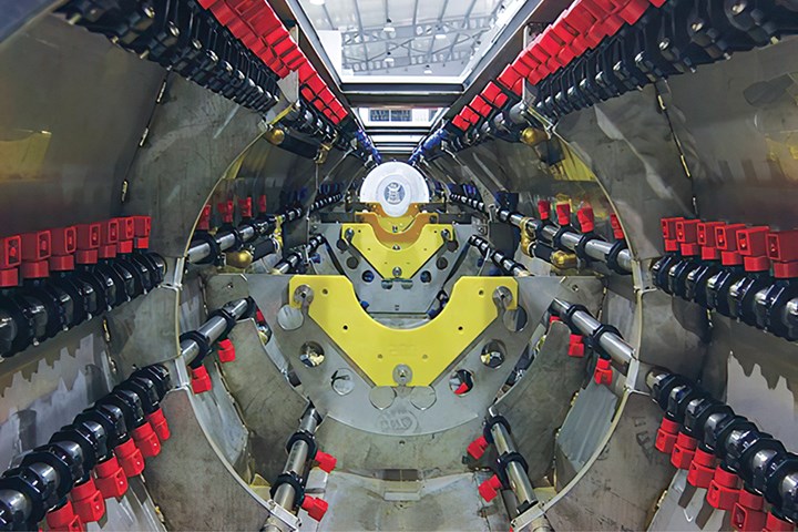
FIG 4 Vacuum cooling tank with external spray nozzles (red) and solid pipe supports (yellow). The sturdy yellow pipe supports perform better than rollers, especially with larger pipe sizes. Photo Credit: Conair
Though immersion-style cooling tanks work well with small tubing, they are impractical for large extruded pipe for two reasons: First, larger pipes hold a significant volume of air, which makes them too buoyant to move smoothly through an immersion cooling process. The preferred cooling method for large extruded pipe, external spray cooling, reliably dissipates surface heat while preventing stratification layers in the cooling water — the other problem with immersion cooling.
On larger pipe sizes, usually 10 inches in diameter or greater, external cooling is supplemented by internal air cooling, which is delivered through the die head and flows downstream through the pipe (Figure 5).
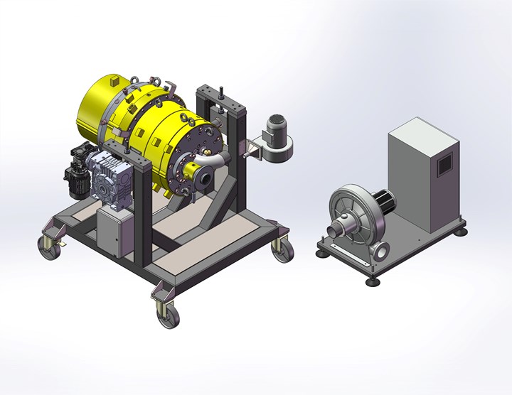
FIG 5 A typical internal pipe cooling system consists of a centrifugal blower delivering a stream of cool air through the pipe head and into the pipe ID. Internal cooling is common on extruded pipe of 10 inches in diameter and above. Internal cooling can save floor space by reducing the length of the required cooling tanks. Photo Credit: Conair
Like other forms of extrusion, successful pipe extrusion is accomplished by understanding and controlling multiple factors in the process. Generally, it is possible to size the pieces of equipment in an extrusion line based on quantitative factors such as dimensions, tolerances and output. However, selecting or building a complementary set of tooling often poses additional challenges due to a range of qualitative factors: polymer characteristics, tooling design and materials, drawdown, process temperatures, cooling methods, cut methods and more.
While extrusion processing norms may sometimes point the way to the right solutions, empirical knowledge developed over time to better understand these qualitative factors can make all the difference in successfully defining and operating a pipe extrusion line.
About the Authors: Ernie Preiato recently retired as vice president, extrusion, for Conair, following a 50-year career, most of which was spent at Conair. Chris Weinrich joined Conair in 2011 and is now general manager, extrusion sales. In his career, Weinrich was also global product manager for Xaloy and spent 14 years with Milacron as product manager. Contact: 724-584-5500; cweinrich@conairgroup.com; conairgroup.com.


Related Content

Formulating LLDPE/LDPE Blends For Abuse–Resistant Blown Film
A new study shows how the type and amount of LDPE in blends with LLDPE affect the processing and strength/toughness properties of blown film. Data are shown for both LDPE-rich and LLDPE-rich blends.
Read More
How Polymer Melts in Single-Screw Extruders
Understanding how polymer melts in a single-screw extruder could help you optimize your screw design to eliminate defect-causing solid polymer fragments.
Read MoreWhy Compression Ratio is Important
Compression ratios have been pretty much standardized over the years, based on what has typically worked before. But there are quite a few variables that must be considered in order to get the optimum performance from your screw.
Read More
How to Estimate and Control Head Pressure
You rightfully worry about melt temperature, but don’t overlook head pressure, because the two are closely linked and will influence line performance.
Read MoreRead Next

Making the Cut: Pick the Right Cutting Technology for Pipe, Tube or Profile
Here is review of popular extrusion cutting technologies, strengths and limitations of each, and common problems and solutions.
Read More
Expanding Profile Extrusion Capacity? Might Be Time to 'Go Dual'
Demand for building products is thriving, and profile extrusion houses are looking to expand capacity. The question they—and possibly you—face is to simply add more single-profile lines or “go dual.” Here’s what you need to consider.
Read More
When to 'Adapt,' When to Retool?
That is the question pipe and tubing processors typically confront when they specify a line for one product, only to have to add to the product mix when business conditions change. Here are some tips to guide you to the right answer.
Read More