
How to Stop Melt Leakage and Carriage Blow-Back
Follow these tips when you have melt leakage around the machine nozzle and sprue bushing or injection-carriage blow-back.


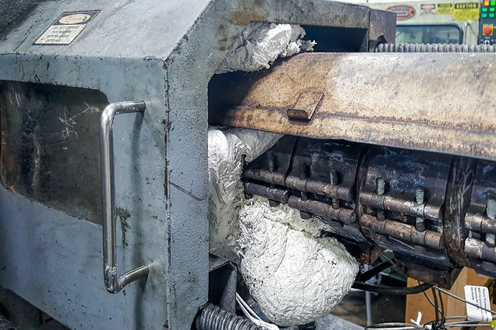
FIG 1 Material leakage caused by carriage blow-back.
I know what you’re thinking: Material leakage and carriage blow-back have nothing to do with tooling. Actually, they have a lot to do with tooling, as well as with the molding machine, the material and the molding process. These are all links in a chain. If you’re out in the trenches and you see a machine barrel coated in plastic, like the one in Fig. 1, you want to know what caused it and how to prevent it from happening again.
Once you establish a process for a mold, if for some reason the screw starts to bottom out during a production run, the plastic has to be going somewhere. Lot-to-lot variations in material are rarely the cause, even with wide-spec resin. The material might be flashing the parting line, slipping over a worn nonreturn valve or worn barrel, filling up a hot-runner manifold, or squirting out between the sprue bushing and machine nozzle tip—none of which are good situations if you want to be profitable.


Monitor your cushion position with an alarm to know when it deviates from the setpoint range.
Hopefully, this article will enforce the necessity to be proactive and monitor your cushion position in real time, with an alarm activated if cushion deviates from the allowable setpoint range. That is the best way to be alerted to potential material leakage or blow-back long before it becomes a major problem. Monitoring the shot weight on an hourly basis is also a good indicative procedure because if you chart the weights, you can see an upward or downward trend that can alert you to correct the problem before the parts go out of specification or before leaking material does severe damage. The most common knee-jerk reaction among floor personnel in response to a decline or loss of cushion is to increase the shot size. If the part has sink or shorts, adding more material to the shot days or weeks after the ideal process was established will usually only make the situation worse.
Once you have discovered there’s a problem, here are some steps to help determine the root cause. I listed them in order from the most likely and easiest to check to the least likely and more difficult to correct.
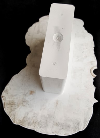
FIG 2 A Parting-line flash means that injection pressure is blowing the mold open.
1. Check the part and the runner to see if the injection pressure is blowing the mold open or pushing an unsecured sprue bushing back, as shown in Figs. 2A, 2B.
2. If it is a hot-runner mold, purge a partial shot under low pressure with the mold open to make sure none of the nozzle tips are obstructed. Note: I can’t stress enough how important it is to make sure the available injection pressure during production is only slightly higher than the pressure established to adequately fill and pack the cavities. A pressure much higher than what is needed is an invitation to flood the hot-runner manifold with plastic, especially at startup.
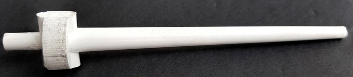
FIG 2 B “Blow-back” occurs when injection pressure pushes back an unsecured sprue bushing.
3. Check the machine carriage for misalignment. Retract the carriage and then advance it forward until it hits the sprue bushing. Does it jump up, down, left or right? In addition to potentially causing material to squirt out, misalignment will damage the face of the sprue bushing seat, making material leakage that much more likely.
Check the contact between the nozzle tip and the sprue bushing.
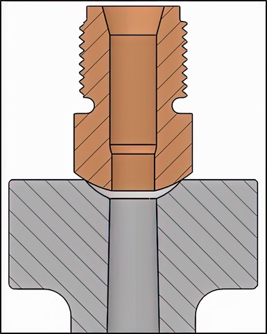
FIG 3 A ¾-in. machine-nozzle tip orifice on a ½-in. sprue-bushing orifice encourages blow-back.
4. Check whether the sprue bushing (or hot bushing) in the mold has, for example, a ½-in. spherical radius but the setup man used a machine nozzle tip with a ¾-in. spherical radius, as shown in Fig. 3. Upon injection, the air gap between the two surfaces will immediately fill with molten plastic and act as a hydraulic cylinder pushing the carriage back.
5. Check whether the orifice of the machine-nozzle tip is just slightly smaller than the mold’s sprue-bushing orifice. The reason why this is so important is a little technical: When a nozzle-tip orifice is the exact same diameter as the sprue-bushing orifice diameter, as shown in Fig. 4A, the pressure inside the flow channel is uniform—meaning the pressure is exerted evenly in all directions. Let’s say, for example the orifice size was 3/8 in. and the plastic injection pressure was 25,000 psi. Use the formula Force = Pressure × Area (F = P × A) to determine how much force is generated. In this example we get 25,000 × (π × (3/16)2) = 2761 lb, or 1.4 tons, pushing against everything—including the injection carriage.
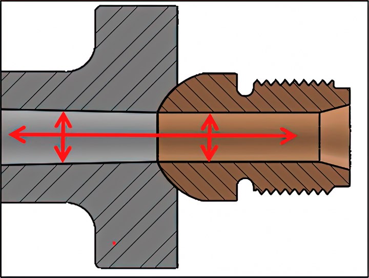
FIG 4 A Machine-nozzle tip with orifice diameter the same as the sprue-bushing orifice.
A machine-nozzle tip that is 1/32 in. (0.0312 in.) smaller than the sprue-bushing orifice is (unfortunately) the industry norm. When the orifice of the nozzle tip is smaller than the orifice of the sprue bushing—which, as I just mentioned, is almost always—plastic pressure is also applied to the exposed face of the nozzle tip – directly in line with the machine carriage, as shown by the yellow arrows in Fig. 4B.
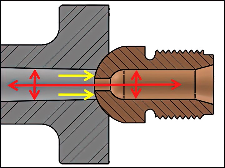
FIG 4B Machine-nozzle tip with orifice diameter excessively smaller than the sprue-bushing orifice.
If the orifice of the nozzle tip in this example were, say, 1/8 in., when you use the same formula, F = P × A formula, the exposed surface adds another 1.2 tons of pressure pushing directly against the carriage, for a combined force of 2.6 tons. If the molding machine’s nozzle-touch force is not safely greater than that, it’s probably the reason why you have carriage blow-back. Note: Having the correct size machine-nozzle tip also reduces the pressure drop of the material going through the nozzle and provides additional injection pressure available to fill and pack out the cavities.
6. Check the contact between the machine’s nozzle tip and the sprue bushing. There are many factors that can cause a mismatch between them and ultimately result in material leakage or carriage blow-back. One of the biggest culprits is the lack of manufacturing precision on the spherical radius of the sprue bushing and machine-nozzle tip that you purchased from your component supplier.
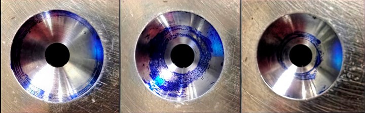
FIG 5 Three different nozzle tips blued off against a sprue bushing.
I took three brand-new nozzle tips made by three different component suppliers and blued them off against a brand-new sprue bushing, as shown in Fig. 5. One blued off on the outer perimeter, one in the middle, and one near the orifice. Ideally, you want the nozzle tip to seal off on, or very close to, the sprue-bushing orifice, like the picture on the right of Fig. 5. That will reduce the chances of material leakage, as well as air infiltration. If the nozzle tip is out of specification, like the picture on the left of Fig. 5, it can act the same way, and have the same results, as using a ¾-in. nozzle tip on a ½-in. sprue bushing.
Pressure-sensitive film also works extremely well for checking the contact between these two components. However, it requires the sprue bushing and nozzle tip to be at room temperature, otherwise the film will melt.
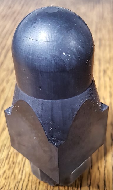
FIG 6 EDM electrode for repairing a sprue-bushing seat.
If you find a radius mismatch, you have a few options to correct it. The easiest is to swap out the nozzle tip and check the contact again. The long-term solution is to either grind the machine-nozzle tip to a 0.496-in. spherical radius, or EDM the sprue-bushing seat to a 0.504-in. radius, using an electrode such as the one shown in Fig. 6. Do not trust the carbide cutters sold by some molding supply companies specifically to reface a nozzle tip or sprue-bushing seat. I’ve heard reports that they are not very accurate.
A couple of manufacturers polish the face of their nozzle tips. They’re very pretty, but less than useful. If you sand-blast the face of a nozzle tip, you get a better seal-off against the sprue bushing. The textured finish will also give you an excellent visual indication of how the tip is seating, as well as whether the injection carriage is aligned—or misaligned, as in Fig. 7.
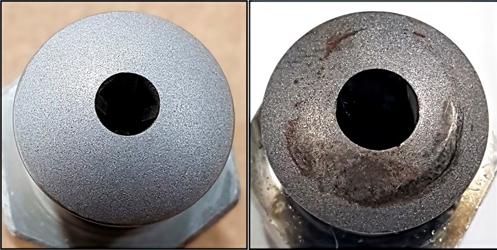
FIG 7 A rough finish on a nozzle tip will indicate how well it is seating.
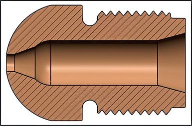
FIG 8 A general-purpose nozzle tip with reduced land length.
7. Check the molding machine. Some machines allow the user to vary the nozzle-touch force. Is it set to the maximum value? Most machines use either a hydraulic cylinder, servo motor, or a spring pack to establish the nozzle-touch force. Are you sure the carriage is being pulled forward the correct amount and with constant pressure? If you are in doubt as to the reliability of the machine’s nozzle-touch force, there are several companies that offer compression pressure sensors (load cells) for accurately determining what the true value is. It is worth noting that many molding machine manufacturers use a nozzle-touch force based on the weight of the carriage. It should be based more on the screw’s maximum injection pressure. If you’re injecting at 35,000 psi into a ½ in. orifice—regardless of the size of the molding machine—you are generating a minimum of 3.4 tons of pressure that is trying to blow the carriage back.
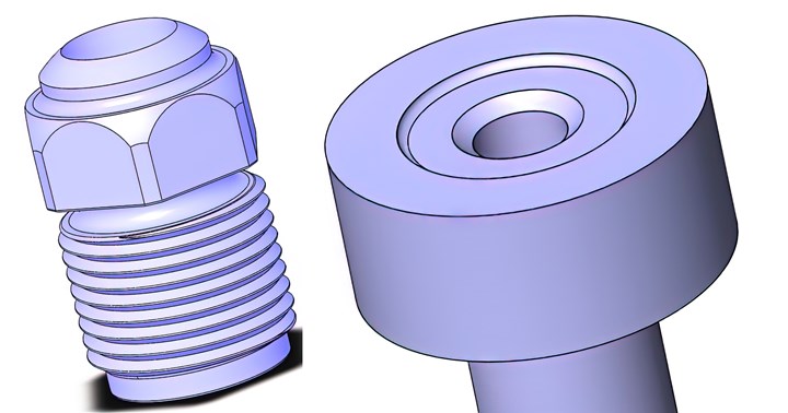
FIG 9A, 9B Methods of reducing contact area. (All images courtesy of Jim Fattori)
8. Determine why the peak injection pressure is so high and consider ways to reduce it. Is the gate or runner undersized? Is the flow length in the cavity too long for the melt-flow index of the material and the wall thickness of the part? Is there adequate venting? Is there any chance there is a mixing-nozzle body or a nozzle tip with a tramp-metal screen pack still installed from the previous mold? Is the melt temperature of the material within the manufacturer’s recommended range? (See John Bozzelli’s Dec. 2016 article, “Unraveling the Mysteries of Melt Temperature.”) Is the nozzle tip one of the restrictive types with a reduced inner diameter, such as a nylon tip? Are you using a general-purpose tip with an excessive land length? Note: G-P nozzle tips can have their land length reduced, which also reduces their inherent hangup area, by machining the bore as shown in Fig. 8.
9. Reduce the injection velocity right before the screw reaches the transfer position. This can help reduce the peak injection pressure (and required clamp tonnage) that can cause carriage blow-back.
10. Consider reducing the orifice diameter of the sprue bushing (cold or hot). This suggestion relates to the discussion on the internal forces pushing the carriage back as discussed in #3 above. I have used this trick with great success on molding machines with insufficient nozzle-touch force. It does generate a little more shear, and while it can increase the required injection pressure to fill the cavities, it does decrease the amount of pressure trying to blow the carriage back.
11. Reduce the surface contact area between the machine-nozzle tip and the sprue bushing. This can be done either by reducing the diameter of the nozzle tip, as in Fig. 9A, or by adding a counterbore to the sprue bushing (Fig. 9B).
This brings up an interesting fact. The standard depth of an American sprue-bushing seat is 3/16 in. (0.188 in.). My guess is that decades ago, someone thought that 3/16 in. looked about right. It was never questioned. It was never analyzed. And it was never changed. Misumi in Japan uses a depth of just 3 mm or 0.118 in. Meusburger in Austria uses a depth of just 2 mm or 0.070 in. Hasco in Germany uses a depth of just 1.5 mm or 0.060 in.
In my opinion, the U.S. industry needs to reevaluate the best depth for sprue-bushing seats. Why? Because instead of thinking about what’s causing a carriage to blow back, think about what’s trying to prevent it from blowing back. You probably think it’s the machine’s nozzle-touch force. That’s not completely accurate. If you convert the formula F = P × A that I used previously to P = F/A, you’ll see that the pressure the carriage applies to the sprue bushing is equal to the machine’s nozzle-touch force divided by the contact area of the machine-nozzle tip. For example, if the machine has a nozzle-touch force of 2 tons and the contact area between the nozzle tip and the sprue bushing is 0.88 in.2 (which is common for nozzle tips with a ¾-in. radius), the pressure applied to the sprue bushing is therefore 2 tons/0.88 in.2 = 2.8 tons. That’s not a lot of pressure trying to prevent the carriage from blowing back. The thing to understand here is that the more contact area you have, the less pressure you have holding the carriage firmly against the sprue bushing.
For additional information, see my Oct. 2019 article, How to Prevent Nozzle Tip Leaks.
ABOUT THE AUTHOR: Jim Fattori is a third-generation molder with more than 40 years of experience in engineering and project management for custom and captive molders. He is the founder of Injection Mold Consulting LLC in Pennsylvania. Contact: jim@injectionmoldconsulting.com;
injectionmoldconsulting.com


Related Content

Know Your Options in Injection Machine Nozzles
Improvements in nozzle design in recent years overcome some of the limitations of previous filter, mixing, and shut-off nozzles.
Read More
How to Get Rid of Bubbles in Injection Molding
First find out if they are the result of trapped gas or a vacuum void. Then follow these steps to get rid of them.
Read More
What to Do About Weak Weld Lines
Weld or knit lines are perhaps the most common and difficult injection molding defect to eliminate.
Read More
How to Set Barrel Zone Temps in Injection Molding
Start by picking a target melt temperature, and double-check data sheets for the resin supplier’s recommendations. Now for the rest...
Read MoreRead Next

How Polymer Melts in Single-Screw Extruders
Understanding how polymer melts in a single-screw extruder could help you optimize your screw design to eliminate defect-causing solid polymer fragments.
Read More
People 4.0 – How to Get Buy-In from Your Staff for Industry 4.0 Systems
Implementing a production monitoring system as the foundation of a ‘smart factory’ is about integrating people with new technology as much as it is about integrating machines and computers. Here are tips from a company that has gone through the process.
Read More