
Consider the entire melt-delivery system from screw to hot runner as an integral whole if optimization is to be effective.
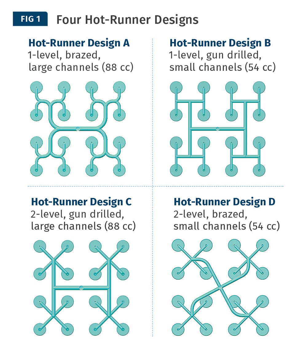
An experimental test of the influence of various elements of the melt-distribution system on processing and part uniformity used four different hot-runner designs, including two each with larger and smaller melt channels.
Hot-runner layout impacted the required fill pressures by up to 6000 psi, or 30-40%. Channel sizes were the major factor. Also, an unbalanced hot-runner system required 10-15% extra pressure to fill out all the parts. Screw design additionally impacted injection pressures by up to 2000 psi or 6-8% of the total fill-pressure requirement.
The best combination of screw and hot runner improved fill balance by 17% over the worst combination. Improved fill balance reduced average part weight 0.05 g and reduced part-size variation by 0.1 mm. The hot runner with the largest channels and the smoothest rounded corners resulted in the best fill balance. Also, the barrier screw produced parts with higher part-weight variation and higher average part weights. Typically, the hot runner is the singular focus to resolve fill-balance issues, but this test shows that the screw itself has a meaningful impact on fill balance.
As injection speed increased, part weight decreased and weight range also decreased. A hot-runner design that reduces pressure drop helps take optimum advantage of injection speed.
Screw B exhibited a 24% improved color-change time compared with screw A, mostly due to reduced channel depths and higher compression ratio. Hot-runner configuration D performed best, as it has small runner sizes and a contoured channel layout. It is well established that color-change times can be enhanced with higher shear rates (smaller channel and flight depths), as this reduces the residence time fo the plastic nearest the barrel and melt-channel walls.
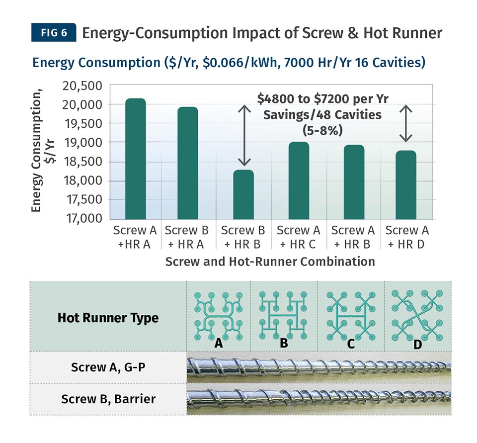
A properly designed melt system is also the most efficient from an energy standpoint. Experimental results showed that a molder could save between $4800 to $7200 per year on a 48-cavity mold of this configuration by using screw design B and hot-runner design B. This represents a 5% to 8% improvement in the required energy.
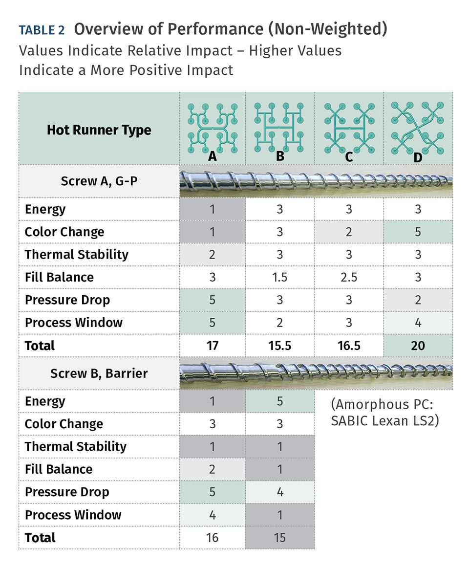
TABLE 2 Overview of Performance (Non-Weighted) Values Indicate Relative Impact – Higher Values Indicate a More Positive Impact
FEA particle trace shows that two apparently balanced hot runners yield quite different fill balances. The colors represent melt particles having the same residence time in the melt stream. The single level H-style manifold creates nonuniform shearing in the hot runner, resulting in unbalanced fill. The X-style melt-channel path creates a much more even shearing profile and resulting filling pattern.
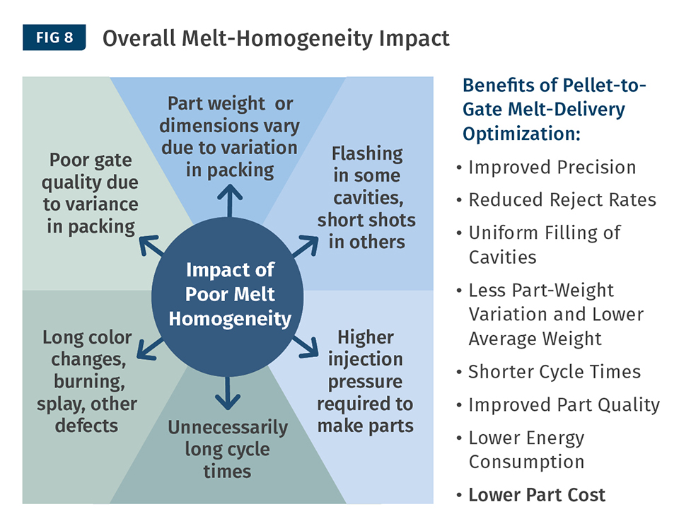
Summary of impacts of melt homogeneity on productivity, quality and economics.


Injection molding: A pellet goes in, and a few moments later a part comes out. Seems simple enough, but what really happens in between these points, and how can optimization of this process create value for you in your operation? What happens in the machine barrel and the hot runner can significantly impact your molding productivity and quality. In this article you will learn how to recognize ways to improve the process of melt creation, delivery and control so that your operation can put more good parts in the box at the end of the day.
Operating a profitable molding facility continues to be a greater and greater challenge. Molding complexity continues to increase due to the demand for thinner, lighter and more complex parts. Customers are asking for increased precision, new resins and additives, multimaterials, higher cavitation, frequent color changes, and faster cycles. As a molding cell is pushed ever closer to its edge of acceptance, any weaknesses in the system become more exposed. These weaknesses can create significantly more difficulties in maintaining OEE (overall equipment efficiency). In these cases, the importance of melt quality and balance of fill, for instance, become more and more critical.


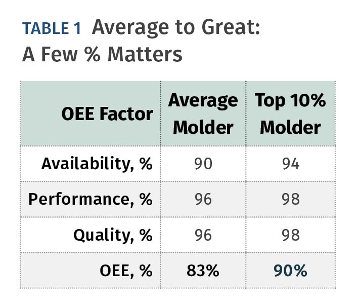
Not many molders consider the entire process from pellet to gate. Frequently, each of the elements in the flow path is optimized independently; and as a result, they could be sub-optimized for the system’s performance. The difference between an average and a world-class molder is only a few percentage points (see Table 1). Could an optimized melt-distribution system help an average molder become a world-class molder?
EXPERIMENT IN OPTIMIZED MELT DISTRIBUTION
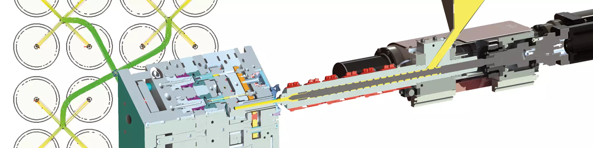
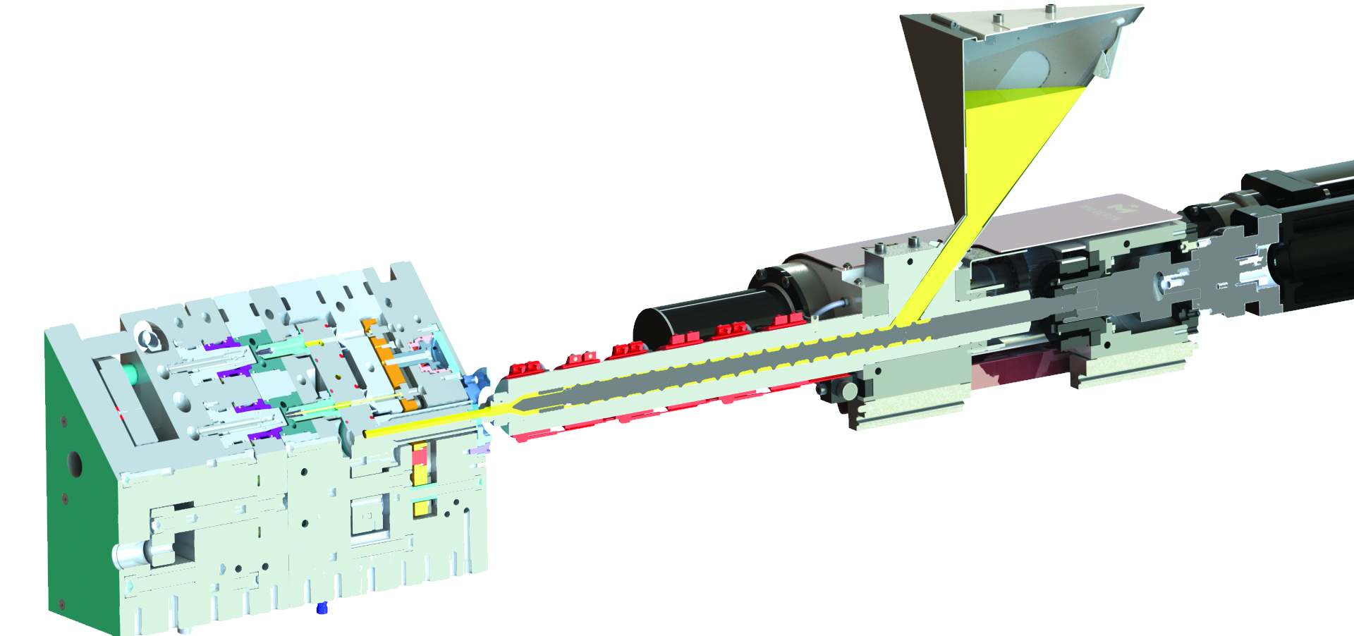
A set of experiments was conducted to determine if an optimized melt-distribution system could create a more homogeneous melt and if that, in turn, would help to improve the overall performance of an injection molding workcell. A 200-ton Milacron-Fanuc Roboshot machine with two different screw designs; a 16-cavity 28-mm cap mold; four different hot-runner configurations (see Fig. 1); and Lexan PC resin were used in different combinations in order to determine the optimized configuration and the difference between the worst and best configurations. Fill balance, pressure drop, part dimensions, color change, energy consumption, and process windows were evaluated to determine the optimal performance.
Could an optimized melt distribution system help an average molder become a worldclass molder?
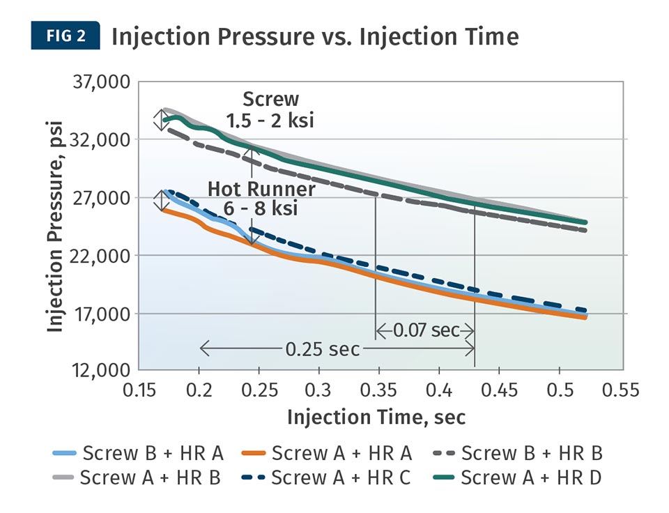
Here’s what was found: Injection Pressure vs. Injection Time: Ideally, a part should be injected with as little pressure as possible, as that reduces clamp tonnage, machinery stress, mold wear, energy consumption, molded-in stresses on the part, flash, ejection issues, and other plastic part issues. If the molding workcell has insufficient injection pressure or if the resistance to fill the part is too high to make a good part, a variety of defects such as sinks, warpage, short shots and dimensional variation can occur. Each of these defects could cause significant quality and uptime issues, which would reduce the overall OEE of the workcell.
The pellet-to-gate system can have a major impact on the required injection pressure to make a good part (Fig. 2). The hotrunner layout impacted the required fill pressures by up to 6000 psi (41 MPa), or 30% to 40%. Channel sizes were the major factor determining the required injection pressure to produce an acceptable part. The balance of fill was also found to have a significant effect on the required injection pressure. An unbalanced hot-runner system required 10% to 15% extra pressure to fill out all the parts. Screw design additionally impacted injection pressures by up to 2000 psi (14 MPa) or 6% to 8% of the total fill-pressure requirement.
Together, an optimized screw and hot-runner design could reduce required injection pressures by almost 50%. On an overall basis, the most optimized melt-distribution and control system reduced injection time by 0.25 sec. This equates to more than a 3% improvement in OEE and almost 6 million additional parts a year.
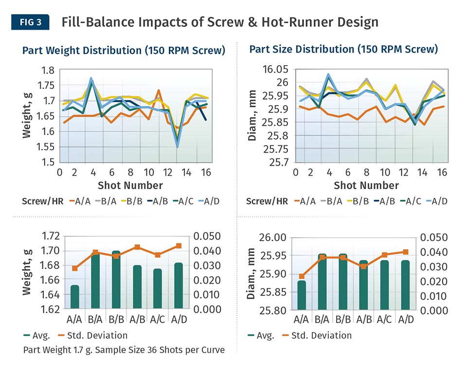
Fill Balance: One of the main objectives of the melt-delivery system is to deliver molten plastic in an identical rheological condition to each cavity in the mold. A well-balanced mold runs a faster cycle, higher uptimes and more uniform parts. The degree of balance is typically determined by molding a statistically significant series of short shots (80% to 90% filled) and measuring the part-weight variation between the molded parts. The smaller the part-weight variation, the better the balance.
In this experiment, two screw designs and four hot-runner designs were evaluated to find the best hardware configuration for fill balance. The best combination of screw and hot runner could improve fill balance by 17% over the worst combination (Fig. 3).
Improved fill balance was also shown to reduce average part weight 0.05 g and reduce part-size variation by 0.1 mm. The barrier-type screw produced parts with higher part-weight variation and higher average part weights. Typically, the hot runner is the singular focus to resolve fill-balance issues, but it can be seen in this test that the screw has a meaningful impact on fill balance, regardless of the hotrunner configuration. In terms of the hot runner, the design with the largest channels and the smoothest rounded corners resulted in the best fill balance. This is because the flow of molten plastic in a runner channel is laminar. The material nearest the walls of the melt channels experiences more shear than the material that flows in the center of the channel. When the plastic rounds a sharp corner, even more shear and momentum loss occurs. A 3% to 5% improvement in OEE could be achieved with the most optimal combination of equipment configuration.
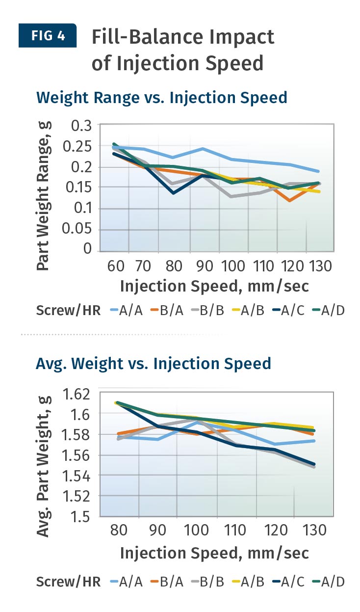
Part Weight vs. Injection Speed: Any reduced variation in part weight improves the performance of a multi-cavity injection molding workcell. It can be seen Fig. 4 that as injection speed increased, part weight decreased and weight range also decreased.
In order to take advantage of this phenomenon, the system must have a lower pressure drop and an equal fill balance. So if the fill balance and pressure drop in the hot-runner system is optimized, it provides an opportunity to further improve the part cost via lower part weights and faster cycles.
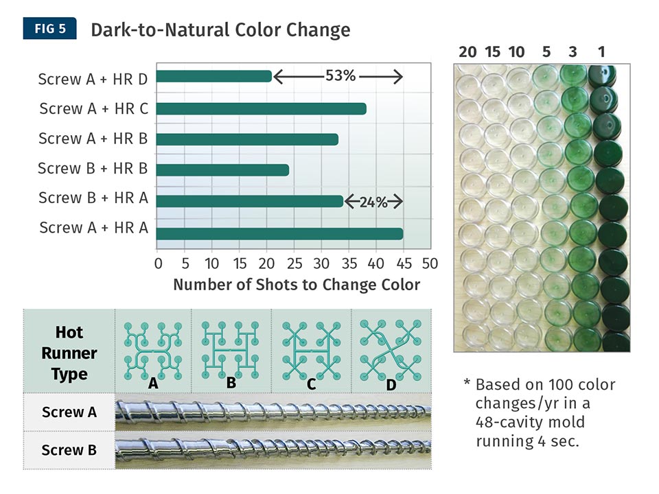
Color Change: The fastest color change can be achieved with hot-runner configuration D and screw design B, although this combination was not tried together (Fig. 5). Screw B exhibited a 24% improved color-change time compared with screw A, mostly due to reduced channel depths and higher compression ratio. Hot-runner configuration D performed best, as it has small runner sizes and a contoured channel layout.
It is well established that color-change times can be enhanced with higher shear rates (smaller channel and flight depths), as this reduces the residence time of the plastic nearest the barrel and melt-channel walls. The contoured melt-channel path and the lack of a barrier section in the screw are also important for short color-change times, as the smooth paths reduce locations where the old color can hang up. Overall, any geometry that promotes “washing out” the previous color will reduce the time it takes to change colors.
Energy Consumption: A properly designed melt system is also the most efficient from an energy standpoint. The experimental results (Fig. 6) show that a molder could save between $4800 and $7200 per year on a 48-cavity mold of this configuration by using screw design B and hot-runner design B. This represents a 5% to 8% improvement in the required energy.
OVERALL SUMMARY OF PERFORMANCE
Table 2 shows the relative performance of each screw and hot-runner combination. Note that no single combination of screw and hot runner was optimal for each variable tested. For instance, the best performing combination for pressure drop was not the best solution for optimal color change or energy consumption. This is why a molder may settle for a “general” solution that has a balance of good results versus a best result for their particular case.
However, the molder should carefully weigh the costs of optimization versus the net benefit it creates. Even a couple of percentage-points improvement in OEE can easily justify the cost of a new hot runner or screw and barrel.
THE KEYS TO EFFECTIVE MELT MANAGEMENT
1. Know the pellets. The first and foremost consideration in optimizing a melt-distribution system is to know the resin you are processing. Each type and specific grade of resin has different characteristics and the system design must take these into consideration for optimal performance. Designing the hardware to match the needs of the plastic is the first and foremost requirement in optimization.
2. System thinking versus equipment thinking. The process of melting the plastic and conveying it to the gate of the mold is a complex interaction of the resin, dryers, loaders, color or additive mixing, injection molding machine, and hot runner. All these parts of the process interact and depend on one another for optimization. Typically, each element is optimized in isolation from the others and, as such, a sub-optimized system is created.
3. Plasticating. The process of creating a homogenous melt and injecting it into the hot runner is a key to being a worldclass molder. The screw configuration has a major impact on melt homogeneity, which is closely related to repeating weight precision and melt-temperature uniformity.
Type B screws exhibited poorer temperature homogeneity and larger temperature fluctuations than the Type A screw when molding this grade of PC resin. The high viscosity of this grade led to a high dependence of homogeneity on screw geometry. The level of homogeneity that is created in the screw is carried into the hot runner and the mold. As the old saying goes, “Garbage in produces garbage out,” so creating a good melt is critical.
4. Screw tip to hot-runner inlet. Although it seems like an obvious fact, the interface between the hot runner and the injection unit must match in size and contact radius. Any mismatch in alignment or size can cause flow restrictions, hang-up spots and pressure loss. Any of these, in turn or together, can reduce OEE via slower cycles, increased scrap or greater downtime.
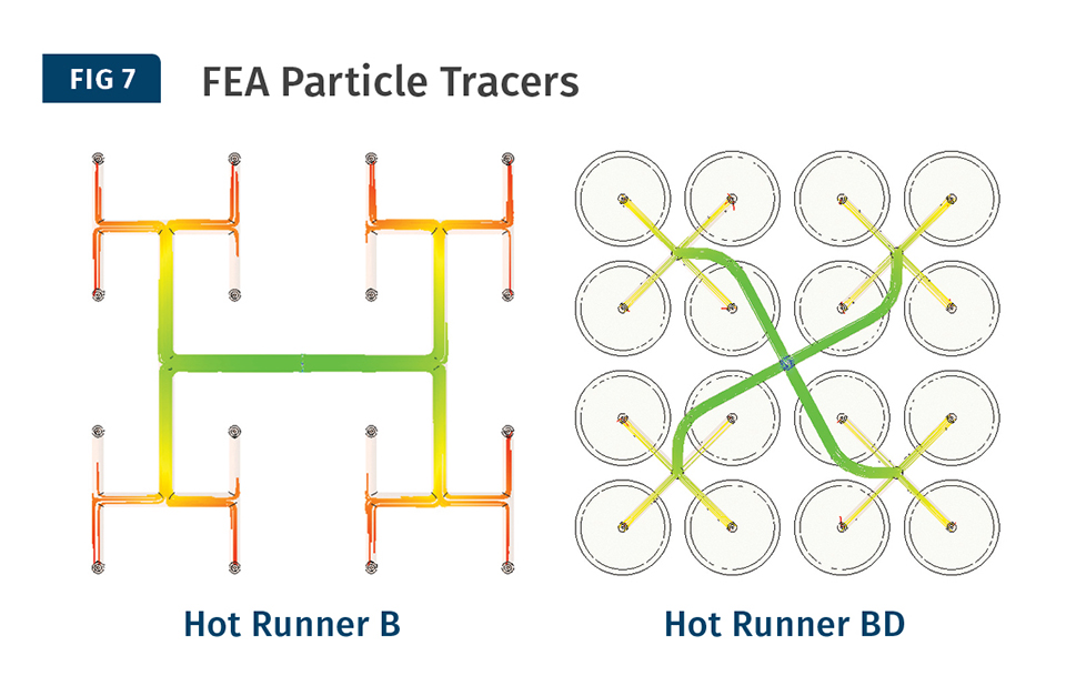
5. Hot Runner. The task of the hot-runner system is to convey the melt to each of the mold cavities in precisely the same state in which it left the barrel/nozzle. The hot-runner system is not able to adjust any melt inhomogeneity. If a hot-runner system is not correctly designed or manufactured, it may cause disruption to production and flaws in parts. A hot-runner system requires uniform temperature distribution along the flow path, minimum possible pressure drop, no hang-up spots, and moderate shear rates. An unbalanced layout of the hot-runner melt channels can lead to many problems in the parts. As can be seen from the 3D particle-tracer images in Fig. 7, two seemingly balanced hot-runner channels can produce different results. The single level H-style manifold creates preferential shearing in the hot runner, which in turn can create problems in the molded parts.
Conversely, the hot runner with an X-style melt-channel path creates a much more even shearing profile and resulting filling pattern. The overall message here is that the screw and hot runner act in conjunction with one another to manage and control melt creation and distribution in the injection molding process. If either the screw or the hot runner is poorly designed, the other element cannot function properly. Failure to optimize the interaction between the screw and hot runner can cause significant problems, resulting in reduced quality, yields and profits.
As in many things, the chain is only as strong as its weakest link. The same can be said of the melt-distribution system. An optimized solution from the pellet to the gate has a material and meaningful benefit to the molder.
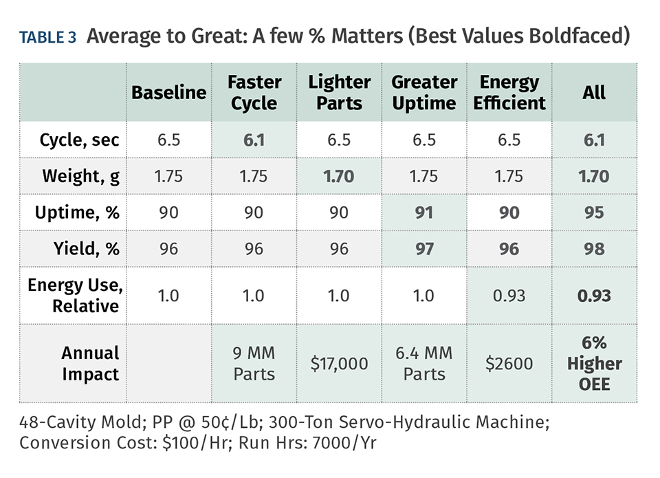
The difference between average and optimal is material to profitability. Variations in dimensions, part weight, balance, gate quality, recovery, and color change can easily make a 1% difference in the system output—scrap, uptime, color change, cycle time (Fig. 8).
In this experimental example, a molder could improve its OEE by 6% simply by optimizing the melt-distribution system. With a 48-cavity PP cap mold based on this experimental design (Table 3), running 0.4 sec faster than baseline could mean 9 million more parts/yr. Saving 0.05 g in part weight could save $17,000 in material cost alone. And only 1% greater uptime could yield 6.5 million more parts/yr. Clearly, retrofitting your existing melt-distribution system is worth considering, as the payback for the new components is in many cases only a matter of a few months, and is meaningful and lasting.
ABOUT THE AUTHOR: Bruce Catoen has held the role of Chief Technology Officer for Milacron since 2014 and has worked in a variety of senior leadership roles at Mold-Masters and Husky since 1988. Bruce is the named inventor on 52 patents. He co-authored the book Selecting Injection Molds (2007) and has published numerous papers in trade journals and presented at many technical symposiums.


Related Content

How to Reduce Sinks in Injection Molding
Modifications to the common core pin can be a simple solution, but don’t expect all resins to behave the same. Gas assist is also worth a try.
Read More
How to Optimize Pack & Hold Times for Hot-Runner & Valve-Gated Molds
Applying a scientific method to what is typically a trial-and-error process. Part 2 of 2.
Read More
How to Stop Flash
Flashing of a part can occur for several reasons—from variations in the process or material to tooling trouble.
Read More
Understanding the ‘Science’ of Color
And as with all sciences, there are fundamentals that must be considered to do color right. Here’s a helpful start.
Read MoreRead Next

Understanding Melting in Single-Screw Extruders
You can better visualize the melting process by “flipping” the observation point so that the barrel appears to be turning clockwise around a stationary screw.
Read More
Troubleshooting Screw and Barrel Wear in Extrusion
Extruder screws and barrels will wear over time. If you are seeing a reduction in specific rate and higher discharge temperatures, wear is the likely culprit.
Read More
People 4.0 – How to Get Buy-In from Your Staff for Industry 4.0 Systems
Implementing a production monitoring system as the foundation of a ‘smart factory’ is about integrating people with new technology as much as it is about integrating machines and computers. Here are tips from a company that has gone through the process.
Read More