What's Controlling Your Cycle Time: Part 3
Follow these guidelines to maximize your profits.


Recently I received a short video of a client’s mold running in production. After watching the video, I shook my head and wondered how this molder was still in business.
It was a simple cold-runner mold, with a full-round runner and a cold sprue feeding the small cavities. My initial suggestion to replace the cold sprue with a hot bushing, to help reduce the cycle time and save on the expensive virgin-only material, must have fallen on deaf ears. The second thing I noticed was the mold-opening stoke was about 12 in. long. The cold sprue is only 3 in. long! Since the parts and runner don’t rotate upon ejection, the mold-opening stroke could be reduced by two-thirds, leaving an opening of about 4 to 5 in. This reduction will save about 1 sec of cycle time. The current cycle is 15 sec, so that would equate to about 7% more profit—simply by setting the appropriate mold-open stroke. There’s also the savings in machine maintenance and energy costs by not making the machine work so hard. Setting the optimal mold-open stroke is Processing 101.


Set the proper ejection stroke to minimize the cycle time.
The third thing I noticed was the multiple ejector strokes. Why? The parts fall free on the first stroke! Some processors habitually use one additional ejector stroke beyond what is required to eject the parts. They call it their “insurance policy.” Unless there are some very long, thin, or fragile protruding core pins, or some other component that can easily get damaged if a part sticks, the insurance policy should be the mold’s low-pressure close settings—not additional ejector strokes that wear out the guided ejection system and the ejector-pin bore holes faster than necessary. If there is a problem with the mold, fix it. Working around a problem is usually to nobody’s benefit.
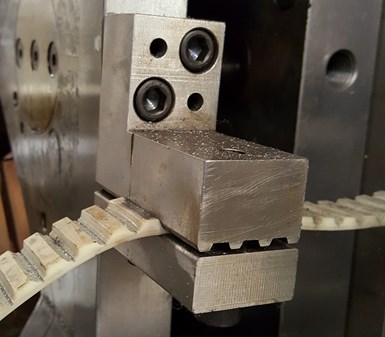
FIG 1 No-stretch timing-belt puller. (All Photos: J. Fattori)
Insufficient Ejection Stroke
Before I discuss the various causes of parts and runners sticking on pins and other components during ejection, which needlessly extend the cycle time, I want to discuss an ejection problem that occurs every now and again—insufficient machine ejector stroke. That problem should be checked before the mold is even hung in the press. Actually, the problem should be checked in the mold-design stage—before it becomes a problem. There are two solutions available for this oversight. The first one being to run the mold in a larger machine with a longer ejection stroke, which will increase the part cost and reduce profits. The second is to install some type of device that will advance the ejector plates their full amount during the mold-opening stroke, even when a smaller machine is incapable of doing so.
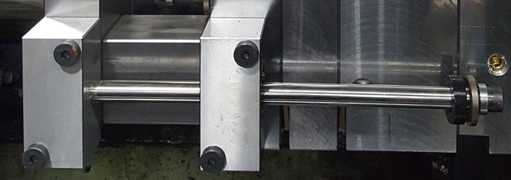
FIG 2 Range-bolt puller.
Assuming there is no room available to add any devices inside the mold, such as range bolts connecting the A-plate to the ejector plates, there are several methods to accomplish this outside the mold. These methods include the old-school roller chains (which I do not recommend), no-stretch timing-belt chains as shown in Fig. 1, standard range bolts as shown in Fig. 2, various types of range bars as shown in Fig. 3, telescoping range bars as shown in Fig. 4, and hydraulic cylinders as shown in Fig. 5, which are typically used for large, heavy plates.
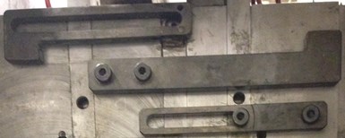
FIG 3 Two types of range-bar pullers.
With the exception of the hydraulic cylinders, all of the other methods mentioned are strictly pullers. They are limited to a single forward ejection stroke and require the return pins to push the ejector plates back into position. Conversely, hydraulic cylinders can advance and retract as many times as the machine’s core-pull sequencer allows.
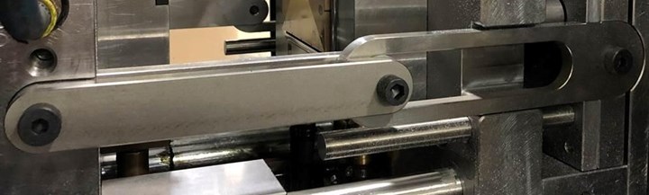
FIG 4 Telescoping range-bar puller.
Verify the machine’s ejector stroke during the design stage.
Parts Sticking
Parts sticking on the ejector pins or other mold components during the initial mold sampling are typically caused by mold-design errors. Parts sticking after thousands of hours of production are typically caused by wear or gassing. Mold-design errors are the more common cause of parts sticking.
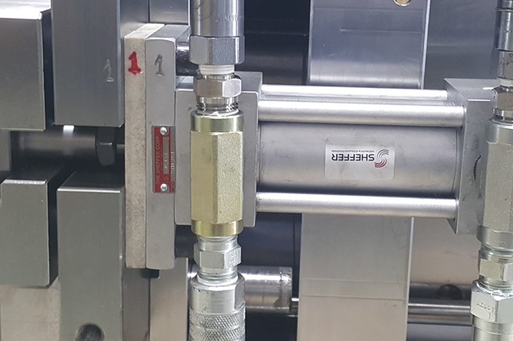
FIG 5 Hydraulic cylinder puller.
Parts can stick on the ejector pins for various reasons, especially if they are located in the corners. Figure 6 shows a worst-case scenario, where the pins were not only in the corners, but were form-ground with a 90° angle. When the parts go back and forth, and back and forth on the ejector pins, I call that “going for a ride.” Shrinkage is often the culprit for parts sticking on ejector pins. As the parts cool and shrink, the plastic grabs onto two opposing components. Most mold designers locate ejector pins in the corners, believing that is where the part will hold on the tightest—and they would be 100% correct. But it’s also where the tool steel is the hottest. A better design is to locate a water line, baffle, or bubbler in the corners of a core and locate ejector pins on either side of that water channel.
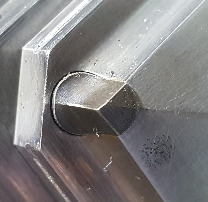
FIG 6 Ejector pin in the corner of a part.
Avoid ejector pins in the corners of a part.
Parts sticking to ejector pins is also a common occurrence when the ejector pins are slightly embedded into the parts. The pins may be a little too long, or ejection is occurring a little too early, pushing the pins into the parts. A simple solution is to make sure the pins are flush or slightly beyond the surface of the part (recessed into the mold) and use larger-diameter ejector pins. However, sometimes longer pins are intentional, as specified on the customer’s 2D part drawings with notes like, “Ejector pins to be flush to 0.003 in. below the surface of the part.” In this circumstance, putting the ejector pin inside a bushing or a short sleeve that protrudes the required amount, will help prevent the parts from sticking onto the ejector pins, as shown in Fig. 7.
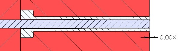
FIG 7 Extended pin and sleeve.
For a host of terrible reasons, processors will work around a molding issue instead of having the mold corrected. Parts sticking to ejector pins or other components is one of those issues. One method a processor will use to work-around the problem is less then desirable. Machines with hydraulic ejector systems can be programmed to slap the ejector plates up against the back of the B-retainer plate. The sudden impact can dislodge parts from whatever components are causing the hang-up. But it’s not what one would call a root-cause solution, and the sound of two plates banging together is never welcome. In fact, the decibel level can be above the OSHA maximum allowance for an 8-hr exposure period. The same slamming scenario is also commonly used to eject the runner in a three-plate mold.
Another cause for parts sticking is when you have two opposing lifters and there’s nothing keeping the part centralized. As the ejector plates move forward, the part will try to stick to one lifter or the other. The best solution is to have a two-stage ejector system, where the ejector pins continue to advance after the lifters have stopped. But that is an expensive, if not an impossible solution when the mold is already built.
A less expensive solution is to add a pointed, truncated, or bull-nosed ejector pin to keep the part centralized while the lifters spread apart, as shown in Fig. 8. If the part is edge-gated, a pin can be added to the runner, as close as possible to the gate. That often solves the problem and avoids having to add a pin, boss or rib on the molded part to keep it centralized.
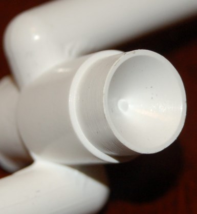
FIG 8 Bull-nosed ejector pin.
Another simple, yet effective trick is to use “delayed retraction” of an ejector pin or two. This requires that the delayed pins have a “positive return,” meaning they need to be pushed back into their retracted position when the mold closes. The retraction of a pin is delayed by allowing it to “float” forward in the ejector plate. When the ejector system retracts, the delayed pin remains slightly forward and pushes the parts off the other pins. Figure 9 is an example of this idea. This method works best when something, such as an O-ring, applies resistance to the delayed pin(s). Figure 9 shows a design using a spring-loaded ball plunger, seated in a groove in the delayed pin to apply the resistance.
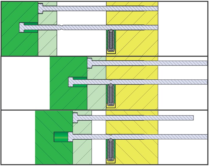
FIG 9 Delayed retraction of an ejector pin (top-bottom: retracted, advanced and delayed positions).
Another source of parts and runners sticking on ejection is when a “Z-Pin” is used to pull the sprue out of the bushing in the A-plate, as shown in Fig. 10. When you use this type of pin, it must be oriented in such a way as to allow the parts and runner to fall freely. There are several other methods available to aggressively pull the sprue out of a sprue bushing without having to use a Z-pin.
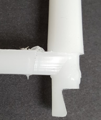
FIG 10 Z-pin sprue puller.
Split pins are another area where parts can hang up during ejection. The ones that don’t hang up are the ones that are not designed correctly. These often cause a blemish or a sink mark on the surface of the part. Unfortunately, the ones that are designed correctly, as shown in Fig. 11, can cause the tab formed in the split pin to hang-up. It’s a Catch 22, unless the mold has two-stage ejection.
For molds that have a lot of miles on them, down-flash can cause the parts or runner to hang up during ejection, as shown in Fig. 12. Cold wells, bosses on runners, and deep ribs are prone to down-flash on ejector pins because the trapped gasses escape down their sides and erode the steel. The short-term solution is to replace the pin with a larger size—typically 0.005 in. larger.
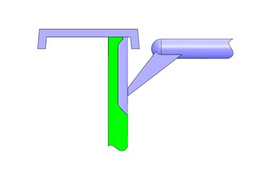
FIG 11 Split pin.
The long-term solution is to use an ejector pin that is smaller than the area it is ejecting, as shown in Fig. 13. This method helps reduce the amount of gas going down the sides of the ejector pin. As you should know, the depth of a boss near a tunnel gate is extremely critical. I refer you to my January and February 2018 Tooling Know-How columns on tunnel gates for more detailed information. However, the depth of a boss on a runner is much less critical, but still worthy of some consideration.
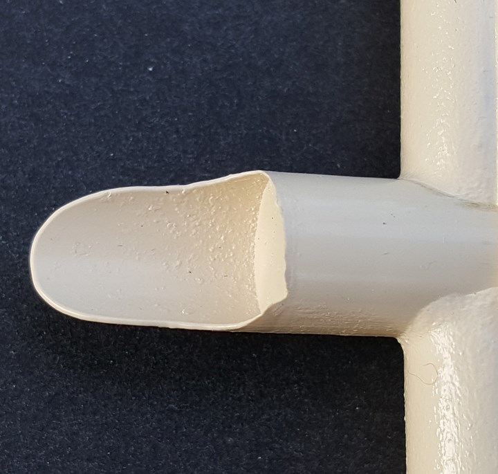
FIG 12 Down flash and pitting.
There are no hard-and-fast rules on what dimensions to use for these types of bosses. I have seen bosses that were very wide, narrow, short, long, straight and tapered. It seems every mold designer has individual preferences. The boss dimensions noted in Fig. 13 are based on past experience and have proven to work well with most material types. The boss could have a reverse taper if used as a puller.
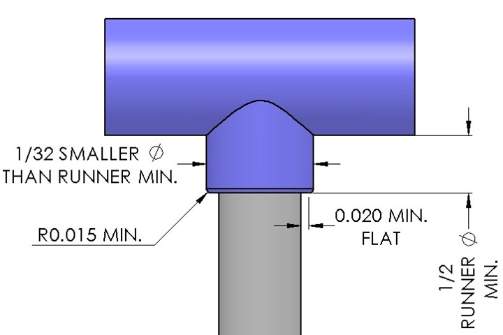
FIG 13 Ideal runner boss design.
Next month, we will look at additional areas to help reduce a mold’s cycle time.
ABOUT THE AUTHOR: Jim Fattori is a third-generation molder with more than 40 years of experience in engineering and project management for custom and captive molders. He is the founder of Injection Mold Consulting LLC in Pennsylvania. Contact: jim@injectionmoldconsulting.com;
injectionmoldconsulting.com
Related Content

Are Your Sprue or Parts Sticking? Here Are Some Solutions
When a sprue or part sticks, the result of trying to unstick it is often more scratches or undercuts, making the problem worse and the fix more costly. Here’s how to set up a proper procedure for this sticky wicket.
Read More
How to Stop Flash
Flashing of a part can occur for several reasons—from variations in the process or material to tooling trouble.
Read More
How to Set Barrel Zone Temps in Injection Molding
Start by picking a target melt temperature, and double-check data sheets for the resin supplier’s recommendations. Now for the rest...
Read MoreRead Next

What’s Controlling Your Cycle Time? Part 1
Follow these guidelines to maximize your profits.
Read More
What’s Controlling Your Cycle Time? Part 2
Follow these mold-cooling guidelines to maximize your profits.
Read More
For PLASTICS' CEO Seaholm, NPE to Shine Light on Sustainability Successes
With advocacy, communication and sustainability as three main pillars, Seaholm leads a trade association to NPE that ‘is more active today than we have ever been.’
Read More