
Tooling: Back to Basics on Die Springs Part 1
Some molding shops insist that all of their molds have springs to return the ejector plates. And there are lots from which to choose. Here we’ll focus on compression die springs for injection molds.


I counted more than 30 different types of springs in a well-known supply catalog, each with multiple variations. This month I will focus strictly on one type: compression die springs for injection molds. When you put a load on this type of spring it compresses, or gets shorter. The spring then pushes back against the load, trying to get back to its original uncompressed length. It is such a simple mechanism, and yet is often the cause of significant mold damage and downtime, usually due to improper selection or use.
The most common use of springs in an injection mold is to retract the ejector plates. We need to discuss this particular application because there are two contradictory beliefs. Theoretically, if the mold-closing sequence is adjusted correctly, there is no need to use springs, because the return pins will drive the ejector plates back to their proper position—flush against the stop buttons. If there is a concern about the noise, or potential damage to the return pins, Bellville washers can be installed under their heads to absorb the impact (see my November 2018 column). Alternatively and preferably, the ejector plates should be connected to the molding machine’s knockout system, which then controls the fore and aft position of the plates—also negating the need for springs.


Most modern injection molding machines also allow you to specify how much force to use when advancing and retracting the ejector plates, which is extremely beneficial. If the ejector system starts to bind, gall or seize, it can exceed the amount of force programmed into the machine. An alarm can be set to go off, which can stop the molding cycle and prevent further damage to the mold. Some molding shops will remove the springs when a new mold arrives. They have learned that if even one of them breaks, it puts uneven pressure on the ejector system, which can cause the pins to bind up, or prematurely wear out their through holes. In addition, springs require the machine’s ejection force to be considerably greater, which hampers the ability to prevent mold damage when the ejector system starts to seize.
Despite all of these reasons not to use springs, some molding shops insist that all of their molds have springs to return the ejector plates. They feel it is a safety measure in case a setup person forgets to tie the plates into the molding machine. They also like how it reduces the mold setup time by not having to tie the ejector plates into the machine.
One of the very few instances in which I will specify ejector return springs is if mold damage can occur when the ejector plates are even the slightest bit out of position, such as when there are ejector pins located directly under a cam. In cases like this, I will also add an electrical switch to the ejector plate. This protects the mold by four independent methods: the return pins, the return springs, the safety switch, and the machine tie-in. I learned this lesson when I saw an ejector plate advance ever so slightly due to momentum when the mold opened very quickly. The ejector pins ended up scoring the bottom of the cams. This kind of damage can also occur when assembling a mold on the work bench.
I specify ejector return springs if mold damage can occur when the ejector plates are even the slightest bit out of position.
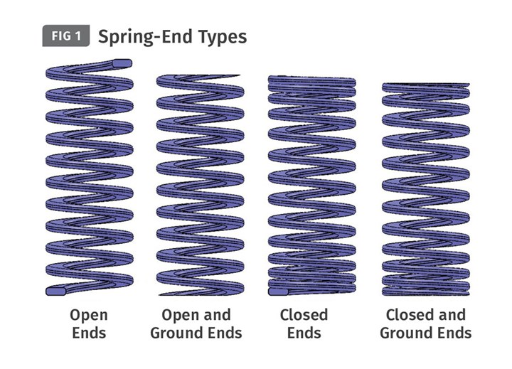
Compression springs can be made from various types and grades of material, such as high-carbon steel, stainless steel, steel alloys, copper, nickel—even plastic. They are available in myriad shapes and sizes. The direction a spring is wound can be either right- or left-handed. The ends of the springs are available in four different conditions, as shown in Fig. 1. They are available with various types of surface finishes for different applications. The cross-section of the wire can come in different shapes, such as round, square, rectangular, rectangular with rounded corners, trapezoidal, or “D” shaped. They are often available in both English (in.) and metric (mm) sizes, as well as ISO, ISO-D and JIS standards. It’s enough to make your head spin. So how does a mold designer know what kind of spring to select?
Most of the leading mold-component suppliers offer die springs made by The Barnes Group under the trade name Raymond. Seemingly, then, our industry has selected this brand as its standard—or at least the more well-known suppliers have. That’s not to say that a few mold-component suppliers don’t offer other brands of die springs. In my experiences I found others that were at least equivalent from an engineering point of view.
People in the metal-stamping business probably know more about springs than in any other industry. Their dies are punching out hard metals at extremely fast rates. Springs are essential to their business. Fortunately, we don’t have to be spring experts. But we do need to know how to select and use them properly.
Most commercially available springs are made of 6150 chrome vanadium alloy. The shape of the wire is trapezoidal, and the ends are closed and ground, which means the end coil loop is aligned perpendicular to the length and then ground flat. They are right-hand wound, meaning the last coil will stop in a counterclockwise direction, and they are shot peened to improve their fatigue life. Lastly, they are coated to resist corrosion.
The first thing you need to know about springs is that their strengths are color coded, as shown in Fig. 2. These are the color codes for U.S. (in.) springs. The other spring classes, such as US Heavy Duty, ISO, ISO-D, and JIS use a different color coding. Not only is this confusing, it’s dangerous. If you’re a molder and you get a mold that was built offshore, or run by someone else, it would be wise to throw out the existing springs and replace them with ones you know have the correct rating.

The blue, medium-duty springs are the most common strength used in injection molds. Occasionally, you might see a red medium heavy-duty spring, or even a gold heavy-duty spring—but not very often. If the mold is large and the ejector plates are heavy, I personally prefer to use blue springs with a larger diameter, or use more of them than I would use red springs having an equivalent total force rating. However, if the required amount of compression is very small, a red or gold spring can be the better choice.
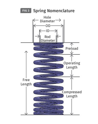
Figure 3 depicts some basic nomenclature that you need to know when selecting a spring:
• The Free Length is the measurement before the spring is subject to any operating force or load.
• The Hole Diameter matches an industry-standard drill size and is larger than the OD, or outside diameter of the spring. It accounts for the expansion of the spring when compressed, as well as the manufacturing tolerances.
• The Rod Diameter is slightly smaller than the actual ID, or inside diameter of the spring. The rod diameter is also an industry-standard size to match standard stripper bolts and mold pin diameters.
• Preload is the distance the free length of the spring is intentionally reduced or compressed when the mold is assembled. This is one of the most important values to a mold designer. Preloading is required to prevent the possibility of shock loading, which causes a stress surge in the vibration frequency and may result in early spring failure. But it is not the primary reason why it is so important in injection molds. Whether the application is to keep the ejector plates fully back against the rest buttons or to separate an A-Plate from an X1-Plate in a three-plate mold to ensure the desired plate-separation sequence, a load (or preload) must be present prior to the movement of any plate or device. The mold designer has to determine how much force is needed—and that’s not an easy task. For retracting ejector plates, I calculate the weight of the plates and add in a SWAG for the frictional forces of the ejector pins, return pins and guided ejection system. (SWAG is a technical term, signifying “Scientific Wild-Ass Guess.” In other words, a subjective fudge factor based on experience and “gut feel.”)
A more common method is to multiply the weight of the ejector plates by 1.5 or 2. When the springs are used to separate the A-Plate from the X1-Plate on a three-plate mold, I calculate the weight of the A-Plate and add a SWAG for the frictional forces of the leader pins, the gates and the drops. Granted, it’s not a very scientific method, but it usually works well, and there are options if it doesn’t.
Regardless of what die-spring brand you buy, it is wise to check the recommended guidelines directly from the manufacturer.
• The Operating Length or Travel is the distance beyond the amount of preload that the spring is compressed. For ejector plates, it’s the length of the ejector stroke, or the amount the plates move forward. For three-plate molds, it’s a little different. The operating length is the distance between the back of the A-Plate and the front of the X1-Plate when the plates are fully separated. In both cases, the total amount of spring deflection is the preload distance plus the amount of travel.
The most critical factor in selecting the correct spring is to stay within the manufacturer’s guidelines regarding the amount the spring can be compressed. Failure to adhere to those guidelines will result in premature spring failure.
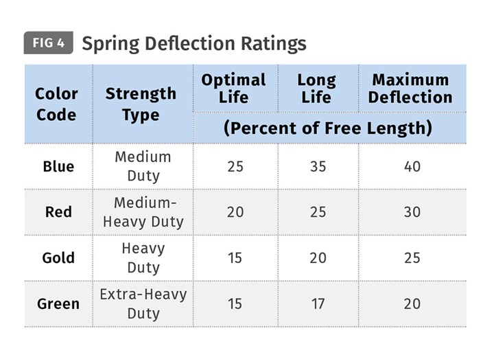
Mold-component suppliers list the percentage of maximum deflection (compression), as well as a percentage range for efficient operation, or for a long or average lifespan. The amount of maximum deflection should be for reference only. Compressing a spring beyond it’s recommended operating range can result in premature failure or be a safety hazard. For some inexplicable reason, these values vary somewhat among suppliers. Figure 4 is straight from the manufacturer’s catalog. Regardless of what die-spring brand you purchase, it is wise to check the recommended guidelines directly from the manufacturer.
ABOUT THE AUTHOR: Jim Fattori is a third-generation molder with more than 40 years of experience in engineering and project management for custom and captive molders. He is the founder of Injection Mold Consulting LLC in Pennsylvania. Contact: jim@injectionmoldconsulting.com;
injectionmoldconsulting.com


Related Content

How to Design Three-Plate Molds – Part 3
There are many things to consider, and paying attention to the details can help avoid machine downtime and higher maintenance costs — and keep the customer happy.
Read More
Design Your Tools for Moldability ... and Maintenance
In the initial design phase, when considering the structure and elements of the tool, are you designing them to be maintenance friendly? Canon Virginia has used this approach and preventive maintenance to make tool replacement a thing of the past. You can, too. Here’s how.
Read More
MPM’s Second Act: Keeping Injection Molding, Moldmaking in the Midwest
Larry Austin’s 35 years at a highly successful injection molding company inform much of what he does and doesn’t want in his second act in plastics owning an injection molding company.
Read More
How to Design Three-Plate Molds: Part 5
There are many things to consider, and paying attention to the details can help avoid machine downtime and higher maintenance costs. In this installment, the focus is on design and placement of sucker/puller pins.
Read MoreRead Next

Why Ejector Pins Break and How to Prevent It: Part 4
In this installment the focus is on bearing length, clearances, keying, and machining.
Read More
Beyond Prototypes: 8 Ways the Plastics Industry Is Using 3D Printing
Plastics processors are finding applications for 3D printing around the plant and across the supply chain. Here are 8 examples to look for at NPE2024.
Read More
People 4.0 – How to Get Buy-In from Your Staff for Industry 4.0 Systems
Implementing a production monitoring system as the foundation of a ‘smart factory’ is about integrating people with new technology as much as it is about integrating machines and computers. Here are tips from a company that has gone through the process.
Read More