Configuring the Twin Screw Extruder: Part 4
For many compounding operations, material is fed to the extruder at the feed throat. This is the case when feeding a single polymer or a blend of polymers mixed with solid additives. Some ingredients, however, present a challenge in feeding. Here’s how to solve to them.


In the previous three articles, we discussed the configurability of the twin-screw extruder. Starting with the barrel sections, we’ve discussed how we can assemble the extruder barrel with the functionality that is required for the compounding process. Then we looked at feeding of raw materials through the feed throat and melting the polymers.
For many compounding operations, all the raw materials can be fed to the extruder at the feed throat. This is true when feeding a single polymer or a blend of polymers to be mixed with some solid additives (such as pigments or low levels of fillers) and pelletized. Some ingredients, however, present a challenge in feeding.


Here, we discuss some raw materials that present difficulties when fed to the feed throat. Additives are raw materials that improve or modify the properties of the polymers. Some of these ingredients can create a blockage in the feed throat or prevent the polymer from melting fully, while others can be damaged by the high forces involved during the melting process.
We will look at how to feed these materials directly into the molten polymer for optimum process effectiveness and product performance.
Fiber Addition
The first materials we will discuss are fibers. Feeding fiber into the feed throat and requiring them to pass through the melting zone can damage the fibers and diminish the property enhancements for which they are being added to the polymer.
Glass, carbon or mineral fibers are commonly added to plastics to enhance the strength of the compounded product. A key characteristic of fiber that enhances the material properties of a compound is the fiber aspect ratio. This is the ratio of the length of the fiber to its diameter.
Processing fibers through an extruder damages those fibers. In the last article, we discussed how the forces generated by the kneading blocks shear the polymer to generate heat. Shear forces are at a maximum during the phase transition from solid to melt. Fibers that are fed through the feed throat and subjected to these same forces would essentially be ground into a powder. The benefits derived from the fibers would be lost as a result of this level of damage.
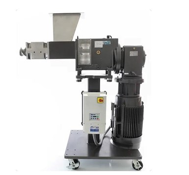
FIG 1 A side feeder pushes solid materials into the molten polymer in the extruder. Photo Credit: CTI/Volker
To lessen the damage caused by processing, fibers are fed downstream after the polymer is molten via a side feeder.
A side feeder, also known as a side stuffer, consists of a hopper and a set of conveying screws. The side feeder (Fig. 1) pushes the solid materials into the molten polymer in the extruder. A combi-barrel section (Fig. 2) provides the connection for the side feeder and venting of any entrained air with the solids.
Fibers are starve-fed into the side feeder using a standard material feeder in the same manner as material is fed to the extruder feed throat. The fibers are conveyed to the extruder and stuffed directly into the molten polymer in the extruder.
Feeding fiber through a side feeder avoids the shear forces generated during melting. The polymer is melted first and then the fibers are introduced and incorporated after the polymer is molten. The shear forces in an extruder are highest when the polymer changes from a solid to a melt. Fibers enter the extruder directly into the polymer melt and can then be gently incorporated, minimizing attrition.
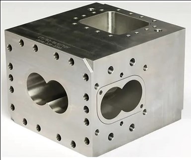
FIG 2 A combination barrel section connects the side feeder with vents for the entrapped air within the solids. Photo Credit: CTI/Volker
Screw Configuration for Feeding Fibers
The unit operations involved with side feeding and incorporation of fibers that have to be considered are feeding and mixing. The side feeder connects to the extruder at the combi-barrel. The screw configuration through the combi-barrel utilizes screw elements similar to those used in the feed throat — long lead conveying elements. These conveying elements should have the standard conveying element profile.
The conveying elements should be placed preferably beginning with one screw diameter or more upstream of the figure eight opening in the side of the combi-barrel and continue into the adjacent, closed barrel section downstream. At this point, the pitch of the screw element can tighten up as needed based on the available space for the overall screw design as shown in Fig. 3.
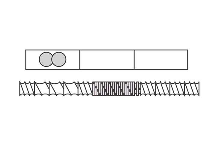
FIG 3 Screw configuration for feeding fibers. Illustration Credit: K. Russell
In general, I do not recommend “SK” type feed elements in this section. The undercut that is beneficial during the feeding of dry, solid ingredients is not wiped the way the rest of the flight is. If you recall, the standard conveying element is self-wiped. The flight from the element on one shaft wipes the flight of the corresponding element on the adjacent shaft. When a feed element is used in a section of the extruder that contains molten polymer, the molten polymer can accumulate in the undercut region. Because there is no mechanism to remove this accumulated polymer, the material can burn creating char that results in gels and black specks.
Once the material is conveyed into the closed barrel section after the side feeder, mixing elements are needed to incorporate the fibers. Gentle mixing is key to minimize any attrition of the fibers. Narrow disc kneading blocks can gently mix the fibers into the molten polymer. Narrow disc kneading blocks provide more distributive mixing compared to wider discs. We will discuss this in more detail in the next article.
A series of forward, narrow disc kneading elements can distribute and incorporate the fibers throughout the polymer. These kneading blocks should immediately be followed by a neutral (90-degree) kneading block. The 90-degree kneading block creates a minor backup of material to ensure the fibers are fully integrated. Some screw designs use only forward conveying kneading blocks to gently mix the fibers, however, this can result in poor incorporation as the fibers may not be fully whetted.
Once the material is conveyed into the closed barrel section after the side feeder, mixing elements are needed to incorporate the fibers.
As the concentration of fibers increases, a reverse pumping kneading block may also be needed to ensure the fibers are fully incorporated. The design of the mixing section for fibers requires attention to balance. The length of the mixing section and whether to use reverse kneading blocks must be balanced against the potential for damage to the fibers. The more work the screw imparts to the material, the greater the potential of fiber attrition.
At the same time, holding back material in the mixing zone by using neutral or reverse conveying kneading blocks creates a gentler mixing action as the amount of material being impacted in that area of the screw is greater. An empty mixing section whips and beats the material more forcefully while a full mixing section cushions the material to some extent.
Low Melting Additives
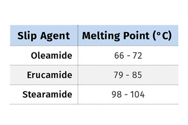
Another group of materials that require downstream feeding are “low melters.” These are additives with a melting point significantly below that of the polymer. Low molecular weight waxes and fatty acid slip agents are examples of low melting additives. The melting point ranges for three common slip agents used in polyethylene films are shown in the table below. Compare these values with melting points of the polymer, for example, 122– 135°C for PE, and the difference in melt points can be problematic.
In addition, these low melting additives melt quickly with minimal shear, becoming a liquid with very low viscosity comparable to water.
Polymers, on the other hand, require significant mechanical energy in addition to heat and melt more slowly across the entire melting section of the screw. The presence of low melting additives interferes with the melting of the polymers. By their very nature, low melters are lubricants. As a result, the polymer slips through the melting section and may not fully melt. Small pieces of polymer can pass through the melting section as solids, resulting in poor quality of the final compound.
Feeding the low melters downstream enables the polymer to be fully molten before introducing these components. The additives are fed through the side feeder and quickly melted. They are then easily incorporated into the polymer stream.
Figure 4 shows a sketch of a generic mixing section. A key point is the use of reverse pumping kneading blocks to provide increased shear and back-mixing to ensure complete incorporation.
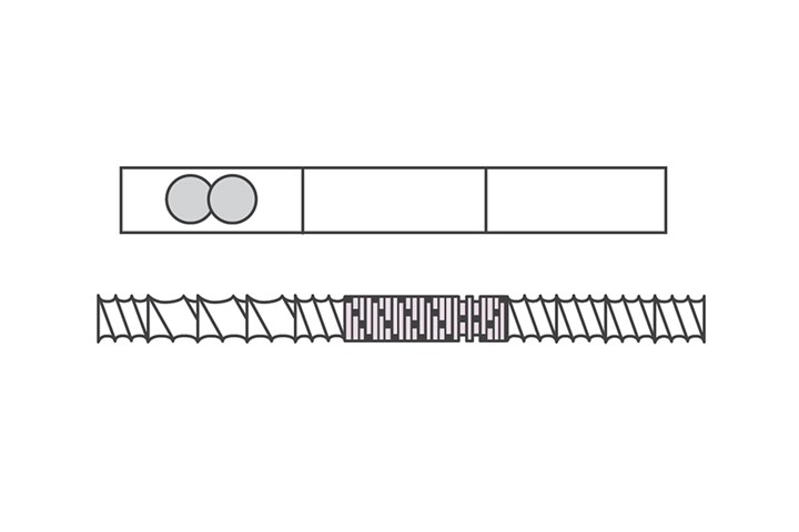
FIG 4 In this generic mixing section, reverse pumping kneading blocks are used to provide increased shear and back-mixing to ensure complete incorporation.Illustration Credit: K. Russell
Feeding Liquids
The final group of additives that we will discuss today are in liquid form. Liquids can be pumped to the extruder and injected directly into the melt. As with low melting additives, liquids are added after the polymer is fully molten. An injection port can be drilled and tapped into a plug for an open barrel or into a separate 1-diameter long injection plate.
The injector consists of a threaded shaft with the same dimensions and threading as used for a pressure transducer or thermocouple. The simplest design is a hollow shaft through which the liquid is pumped. The liquid pressure must be greater than the polymer pressure directly beneath the injector or the polymer can back up into the injector.
For this type of injector, medium pitch conveying elements are best used at the point of injection to ensure the pressure is fairly low while minimizing the potential for pooling of the liquid in the screw root. Injecting directly over mixing elements is preferred but may be difficult depending on the capability of the pump.
A sketch showing a liquid injection set up is presented in Fig. 5. The liquid is pumped through a flow gauge and into the injector. The injector shown here is spring loaded. The pressure generated by the pump must be sufficient to raise the internal plunger opening the outlet of the injector. This arrangement prevents polymer from backing up into the injector by ensuring the liquid pressure exceeds the polymer pressure.
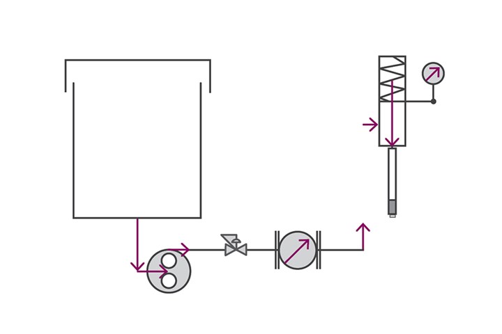
FIG 5 Liquid injection units consists of a threaded shaft with the same dimensions and threading as used for a pressure transducer or thermocouple. Illustration Credit: K. Russell
Once the liquid is injected into the polymer, narrow disc kneading blocks followed by a reverse kneading block or reverse conveying element serve to fully incorporate the liquid into the polymer.
We started this series discussing how the barrel can be assembled and modified to meet the requirements of our process. We’ve now spent three articles discussing how materials are fed to the extruder and melted. In our next discussion, we will look at mixing in a twin screw, the different types of mixing and how the elements function to affect the materials being mixed.
ABOUT THE AUTHOR: Kenneth W. Russell has more than 35 years’ experience working with polymer processing and resin companies. He has expertise in polyolefin polymerization, polymer compounding, reactive extrusion, and film and sheet extrusion. In 2014, he started Optimized Compounds LLC, providing consulting services in reactive extrusion, polymer compounding, product development, process optimization and scale-up with clients worldwide. In 2021, he joined GEM Plastics, a manufacturer of HDPE sheet, providing process engineering, operator and technician training, and materials expertise. Contact: kwrcompounding@gmail.com.
Related Content

Density & Molecular Weight in Polyethylene
This so-called 'commodity' material is actually quite complex, making selecting the right type a challenge.
Read More
Why (and What) You Need to Dry
Other than polyolefins, almost every other polymer exhibits some level of polarity and therefore can absorb a certain amount of moisture from the atmosphere. Here’s a look at some of these materials, and what needs to be done to dry them.
Read More
How to Set Barrel Zone Temps in Injection Molding
Start by picking a target melt temperature, and double-check data sheets for the resin supplier’s recommendations. Now for the rest...
Read More
The Strain Rate Effect
The rate of loading for a plastic material is a key component of how we perceive its performance.
Read MoreRead Next

People 4.0 – How to Get Buy-In from Your Staff for Industry 4.0 Systems
Implementing a production monitoring system as the foundation of a ‘smart factory’ is about integrating people with new technology as much as it is about integrating machines and computers. Here are tips from a company that has gone through the process.
Read More
Processor Turns to AI to Help Keep Machines Humming
At captive processor McConkey, a new generation of artificial intelligence models, highlighted by ChatGPT, is helping it wade through the shortage of skilled labor and keep its production lines churning out good parts.
Read More
Why (and What) You Need to Dry
Other than polyolefins, almost every other polymer exhibits some level of polarity and therefore can absorb a certain amount of moisture from the atmosphere. Here’s a look at some of these materials, and what needs to be done to dry them.
Read More