
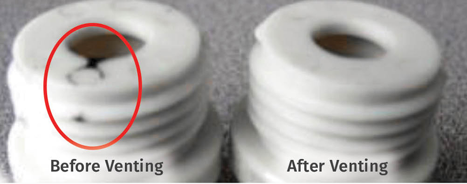
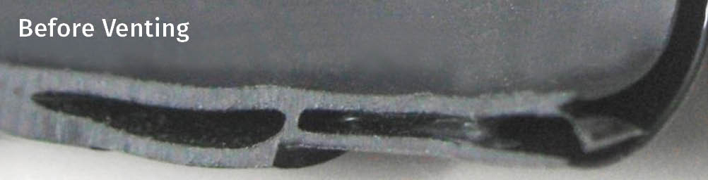
If air is not vented from the mold, it will cause inadequate filling, resulting defects that include short shots, poorly packed-out parts, burning of the plastic, voids in the parts, and dimensional variations.
If air is not vented from the mold, it will cause inadequate filling, resulting defects that include short shots, poorly packed-out parts, burning of the plastic, voids in the parts, and dimensional variations.

If air is not vented from the mold, it will cause inadequate filling, resulting defects that include short shots, poorly packed-out parts, burning of the plastic, voids in the parts, and dimensional variations.
If air is not vented from the mold, it will cause inadequate filling, resulting defects that include short shots, poorly packed-out parts, burning of the plastic, voids in the parts, and dimensional variations.
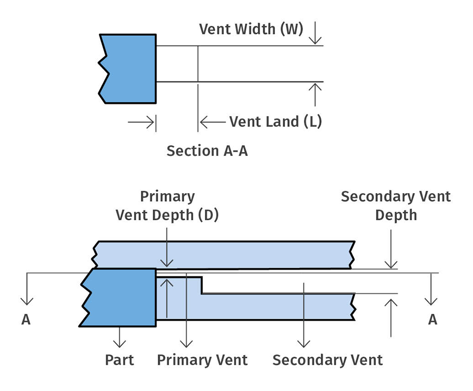
Shown here is the cross section of the mold, indicating the vent area and types of vents. The relieved section that is closest to the cavity steel (and part) is the primary vent. Its dimensions are the most critical.
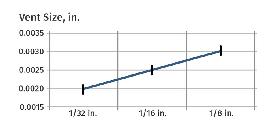
This graph shows the combination of tab thickness and vent depth where flash begins to occur when molding a medium-flow ABS.
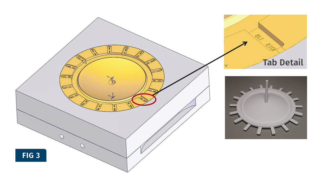
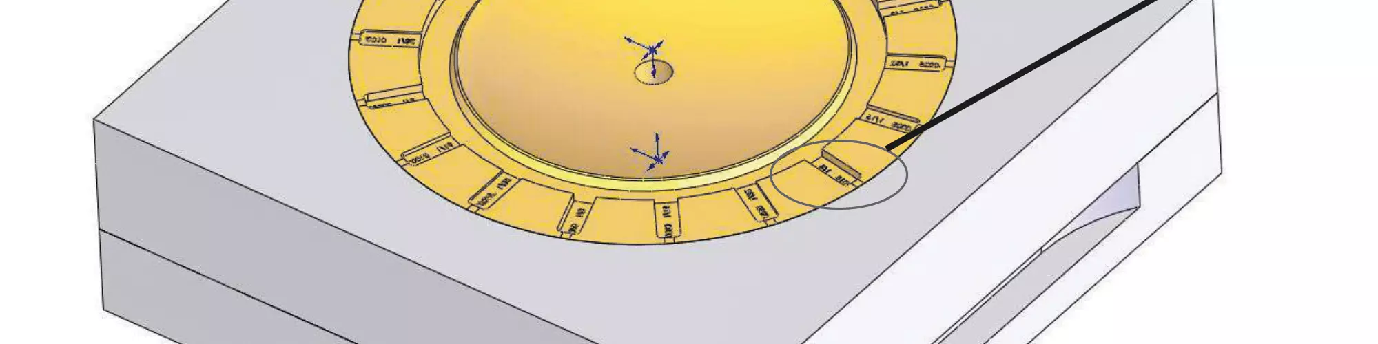
An experimental mold built to study the factors that determine the vent depths was center gated and had 18 tabs of varying combinations of tab thicknesses and vent depths.


In injection molding, air inside the cavity needs to be evacuated for the plastic to fill the cavity. Vents are therefore machined in the cavity blocks in the mold. If the air is not evacuated, it will cause inadequate filling, resulting in several defects such as short shots, poorly packed-out parts, burning of the plastic, voids in the parts, dimensional variation, and so on (see Fig. 1). Over time, the mold steel can get damaged because of the excessive air pressures in the local area at the end of fill or in corners where the air and plastic tend to get pressurized. Lack of vents can also create excessive pressures in the cavity, causing the mold to open sufficiently to cause flash on the parting line.
The vents are machined typically on the parting lines, from where the plastic reaches the end of fill to the outside of the mold. The end of fill here must not be confused with the end of fill during filling of the part. End of fill for this discussion refers to the stopping of the polymer flow in the particular local area. The viscosity of the plastic should be high enough to prevent it from flowing out of the mold through the vent.


Figure 2 shows the cross section of the mold, indicating the vent area and types of vents. The relieved section that is closest to the cavity steel (and part) is the primary vent. The dimensions of the primary vent are the most critical. First, the vent depth (D), should be such that it helps the evacuation of air but not let the plastic escape. Second, the vent land (L), should not be large enough to cause a substantial drop in pressure and prevent air from being pushed out nor should it be so short that the plastic easily finds its way out to the secondary vent. Typical land lengths should be around 0.060 to 0.080 in. (1.2 to 1.5 mm), assuming the vent depth is designed correctly. For larger parts such as car bumpers or doors, the land lengths need to be higher, depending on the volumetric flow rates.
Questions About Mold Venting? Visit the Molds & Tooling Zone.
Third, the vent width (W) should be at least 0.25 in. (5 mm). On the high end, it can be as wide as desired, and in some cases, it can run around the entire perimeter of the part (ring vents). Vents in localized sections that do not run around the perimeter of the part are called spot vents.
The secondary vents are also called vent reliefs. The dimensions of the secondary vents are larger than the primary vent and therefore help in easy transport of air inside the mold out to atmosphere. They are mainly used as a dump area for the air as it exits the mold. Secondary vents should be at least 0.010 in. (0.25 mm). In all cases, the vents must be well polished to avoid any buildup of residue from the gases. The vents must also be draw polished in the direction of air flow.
An article authored by Randy Kerkstra, Venting: Where and How Deep? discussed this topic. The processor needs to have the biggest vents possible so that the plastic can flow into the mold with the least restriction and help with developing a robust process. However, if the vents are even slightly oversized, the result is flash in the part. The moldmaker will then have to weld the area and rework it to get it back to where it was. This is a very difficult and time-consuming process, so moldmakers tend to stay conservative with the vent depths.
For larger parts such as car bumpers or doors, the land lengths need to be higher, depending on the volumetric flow rates.
The dimensions of the primary vents depend on a number of factors. Molders and moldmakers rely on the material manufacturers to provide info on the vent depths. Moldmakers typically follow these recommendations when building an injection mold and tend to stay on the lower end of the recommendation for fear of flashing the mold. Since the recommended vent sizes always come with a disclaimer, FimmTech Inc., with the help of Distinctive Plastics, a custom molder in Vista, Calif., built a special mold to study the factors that determine the vent depths. (The mold is available to material suppliers for determining the vent sizes for their materials.)
EXPERIMENTAL DETERMINATION OF VENT SIZES
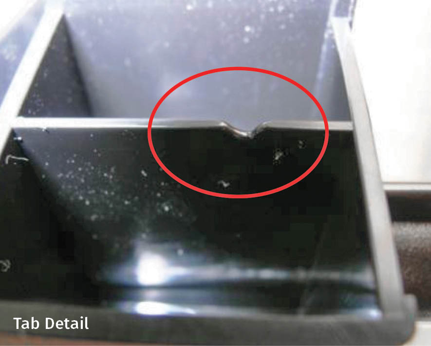
A mold was constructed for a part that is center gated and has 18 tabs of varying combinations of tab thicknesses and vent sizes (Fig.3). The center gate delivered the melt to each of the tabs at the same time. There were three different tab thicknesses: 0.125 in., (3.175 mm); 0.0625 in. (1.587 mm); and 0.0312 in. (0.792 mm). There were six vent sizes from 0.0005 in. (0.0127 mm) to 0.0030 in. (0.0762 mm) in steps of 0.0005 in. (0.0127 mm).
Different materials were molded, and for each tab the minimum vent size where no flash was seen was recorded. The results show primarily that the thickness of the tab also plays an important role in determining the vent size. The thicker tab was able to accept larger vents without flashing. For example, with an ABS material, at the 0.125-in. tab the vents flashed at 0.0030 in.; whereas at the 0.0312-in. tab, the vents flashed at 0.0020 in. (Fig 4). There are two reasons for this. As the plastic is forced into thinner sections, the flow rate of the plastic in the area increased.
The increased flow rate increased the shear rate and led to a reduction in the viscosity, making the plastic flow easier, resulting in flash. The reduced viscosity also allowed a reduced pressure drop, increasing the end-of-fill pressure, resulting in flash. The graph in Fig. 5 summarizes the results.
Good venting leads to robust, repeatable, and reproducible processes.
The published vent depth for ABS is 0.002 in. (0.0508 mm), but the test results from the vent mold showed that a vent size of 0.003 in. (0.0762 mm) is acceptable if the part thickness is 0.125 in. This value was used on several molds successfully. Naturally, parts thicker than 0.125 in. can have larger vents, but there will be a plateau point and the increase will not be linear. Caution is required. Tests on nylons also showed surprising results. The published value for nylons is a vent depth of 0.0005 to 0.0007 in. (0.0127 to 0.017 mm); but for thicker sections, experiments showed a vent depth close to 0.0015 in. (0.038 mm) could be used. In all cases, it is important that proper scientific molding and scientific processing techniques be followed.
Adding vents is an important step in mold design and mold building. Good venting leads to robust, repeatable, and reproducible molding processes. Although material suppliers provide recommendations for vent depths, the they mostly seem to be generic numbers. The method described above is a scientific way of determining vent sizes. For a given mold, the all the vents are usually machined to the same depth. Based on the data above, for maximizing the efficiency of venting, the vents could be machined to different depths based on their location and the wall thickness in the local area.
ABOUT THE AUTHOR: Suhas Kulkarni is the president of FimmTech Inc., Carlsbad, Calif., a firm that provides resources for Scientific Molding and Scientific Processing. The firm provides training, software, and consulting. He has 26 years of experience in injection molding and is the author of the book, Robust Process Development and Scientific Molding, published by Hanser Publications and now in its second edition. Contact: (760) 525–9053; suhas@fimmtech.com; fimmtech.com.


Related Content

Back to Basics on Mold Venting (Part 2: Shape, Dimensions, Details)
Here’s how to get the most out of your stationary mold vents.
Read More
Hot Runners: A View from the Bottom Up
Addressing hot-runner benefits, improvements, and everyday issues from the perspective of decades of experience with probably every brand on the market. Part 1 of 2.
Read More
How to Start a Hot-Runner Mold That Has No Tip Insulators
Here's a method to assist with efficient dark-to-light color changes on hot-runner systems that are hot-tipped.
Read More
Improve The Cooling Performance Of Your Molds
Need to figure out your mold-cooling energy requirements for the various polymers you run? What about sizing cooling circuits so they provide adequate cooling capacity? Learn the tricks of the trade here.
Read MoreRead Next

How to Optimize Pack & Hold Times for Hot-Runner & Valve-Gated Molds
Applying a scientific method to what is typically a trial-and-error process. Part 2 of 2.
Read More
Lead the Conversation, Change the Conversation
Coverage of single-use plastics can be both misleading and demoralizing. Here are 10 tips for changing the perception of the plastics industry at your company and in your community.
Read More
How Polymer Melts in Single-Screw Extruders
Understanding how polymer melts in a single-screw extruder could help you optimize your screw design to eliminate defect-causing solid polymer fragments.
Read More