INJECTION MOLDING: How to Specify an Injection Molding Machine
There are 51 things to consider when spec’ing a controller.
In parts one and two of this three-part series, I offered tips on what you need to consider when specifying the clamp and the injection unit, respectively. In this last installment, the focus is on the controller.
It’s a necessary component of every injection molding machine, and a poor controller can cause major (and often unrecognized) problems, resulting in the loss of hundreds of thousands of dollars a year. Why? Because most controllers are complex, not user friendly, have odd subtleties, and lack uniformity between brands. If molders dealt with only one type of controller perhaps things would be fine, but the fact is that processors usually have to deal with several types, all with different ways of controlling the machine parameters.
The trouble is that controllers supposedly set up the same way actually perform differently. One common complaint that substantiates this is the problems shops have in attempint to make the same part in different presses. Compound this “controller complexity” with the daily pressures of production such as startups, troubleshooting, robot issues, finding lost molds, end-of-arm tooling, documentation, etc., plus 8- to 12-hr shifts and you begin to see the tip of the iceberg. It’s the rare human who can keep everything straight in a typical production environment. If you are saying to yourself, “Not in my shop,” you need to spend more time out on the shop floor. Yes, the machine manufacture knows the controller, but they only deal with theirs, not all the different ones you might encounter every day.
My challenge to you: Start a campaign insisting that machine builders equip all presses sold in the U.S., (if not all of North America) with controllers that have four identical pages in content and layout. These would cover injection with timing sequences; clamp movement and ejection; shot size with screw recovery and barrel-zone temperatures; and a data page listing:
• Actual times for each portion of the cycle,
• Peak pressure during injection,
• Pressure at transfer,
• Actual cutoff position,
• Screw rotate time,
• Cycle time,
• Melt temperature (if the technology becomes available).
Bottom line: Your machine controller is costing you money (big time), causes production issues, and prevents your production-floor personnel from doing the job you want. Agree? Then show this article to your manager to turn up the awareness.
That said, here is my list of general controller criteria:
1. Controller logic is co-developed by a processor and appropriate computer programmer.
2. Screen is robust and can handle 10 years of production wear.
3. Screen is large, bright, easy to see by at least two to three people at one time, to facilitate training.
4. Input values are easy to type in.
5. At all input locations, when highlighted, the allowable range appears when input area is selected.
6. All inputs are labeled clearly in language of choice, not identified by some symbol or number.
7. Scan time is less than 3 milliseconds (0.003 sec).
8. Timers are parallel or in series, whichever your prefer.
9. Values are displayed as units
(i.e. mm/sec) and not percentages.
10. Actual values are provided next
to set inputs.
11. Fill time is provided to at least 0.01 seconds.
12. Pressure at transfer is provided.
13. Provides peak pressure during injection.
14. Controller provides a constant, real-time digital gauge for injection, clamp, ejection, and nozzle-contact pressures.
15. Controller logs process changes.
16. Training time to learn for experienced personnel is less than 3 hr. No adaptive controls—i.e.,corrects on next shot, such as cushion control.
17. Alarms are shown on all screens, most important listed first.
18. Alarms and shuts down if oil filter plugs.
19. Alarms for loss of cushion.
20. Actual positions/pressures, etc. are on-screen.
21. Only the machine manufacturer can tune PID parameters.
22. Furnished with a troubleshooting flow chart for machine malfunction.
23. Plots hydraulic or plastic pressure vs. time (not position) with no break at transfer. Plots at 100 points/sec minimum and axis scales are settable. Plot size is at least half the screen size.
24. Plots may be overlaid and a reference curve retained.
25. Operates in at least three languages (selectable).
26. Provides plastic pressures as well as hydraulic pressure if a hydraulic injection unit is used.
Let’s separate the issues related specifically to temperature control:
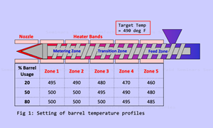
27. PID temperature control for all zones; PID is auto-tuned.
28. Nozzle is PID temperature controlled.
29. Feed throat is PID temperature
controlled.
30. PID uses an ambient reference.
31. Automatic heater-band fault detection with alarm if detected.
32. Heater bands and thermocouples are plug-in type for ease of calibration and replacement and quick barrel change.
33. Furnished with cold-start protection.
34. Oil temperature is controlled to ± 50 C (100 F) if a servo-valve hydraulic unit.
35. Oil preheats at start-up, if hydraulic.
Let’s call the rest of this list
“miscellaneous”:
36. Stores complete mold setups, at least 50 on the machine itself, with other setups stored on inexpensive drives.
37. Program upgrades can be updated quickly, via Wi-Fi (and free) during the first three years.
38. Overall cycle timer or mold-open
timer is available and works in semi-automatic mode.
39. Part-selector option is available based on selectable process monitoring: fill time, recovery, cycle, etc.
40. Safeties can be easily checked for proper function.
41. Allows for velocity profiles on first stage/fill (at least five steps, though more is not necessary).
42. Velocity profiles are set by position, which is graphically mated to its velocity on the screen, not percentages or equal parts of stroke.
43. Velocity is set in units (mm/sec or volume) rather than percentages.
44. Alarms if set velocity is not met,
45. Machine builder provides delta P for proper velocity control, this is listed near set fill or first-stage pressure-limit input.
46. Transfers from first to second stage at setpoint at all velocities.
47. Low-velocity rate for pack control, best to use last profile of fill or first stage.
48. Appropriate task priority during fill or first stage.
49. Velocity linearity is reasonable.
50. Quality-control data is available for the criteria you want, shown graphically and table form and can be downloaded via Wi-Fi.
Any missing? Let me know.
Related Content
Is There a More Accurate Means to Calculate Tonnage?
Molders have long used the projected area of the parts and runner to guesstimate how much tonnage is required to mold a part without flash, but there’s a more precise methodology.
Read MoreCreating a Capable Process Using Process Capability
Know your Cp from your Cpk and how parts can meet dimensional specifications but still not be “capable.”
Read MoreWhat is Backpressure and How Should We Calculate It?
Does using an intensification ratio to calculate backpressure result in an accurate reflection of what’s happening in the barrel? Newer machine technologies have us revisiting an old project with fresh eyes.
Read MoreMelt Preparation Part 1: Melt Temperature Optimization
A homogenous melt is required for consistent part quality, but achieving it requires balancing a number of factors, including barrel usage and temperature as well as screw speed, backpressure and residence time. Learn how to prepare your melt for molding success in this two-part series.
Read MoreRead Next
INJECTION MOLDING: How to Specify an Injection Molding Machine
In part two of a three-part series, the focus is on the injection unit.
Read MoreINJECTION MOLDING: How to Specify an Injection Molding Machine
With the market percolating, more molders are looking at new presses. This series will discuss what you should consider before writing a check, beginning with the clamping unit.
Read MoreHow Polymer Melts in Single-Screw Extruders
Understanding how polymer melts in a single-screw extruder could help you optimize your screw design to eliminate defect-causing solid polymer fragments.
Read More.jpg;width=70;height=70;mode=crop)
