Minimize Sheet Gauge Variation by Roll Design
‘Hour-glass’ sheet gauge can be avoided through a reverse-bending roll design that is out of patent and freely available.
.jpg;width=70;height=70;mode=crop;format=webp)


Over 20 years ago, a reverse-bending roll design was developed and patented to offset chill-roll deflection, permitting the manufacture of flat sheet with greater roll width. Conventional chill-roll deflection under uniform nip loading is proportional to the fourth power (L4) of the roll length. So it takes a significant change in shell thickness to offset the deflection of the nip force as the roll width increases, and this weight also adds to the deflection. The combination of deformation resistance of the polymer and the roll weight itself becomes limiting in controlling sheet gauge as the width increases. This is particularly true of polymers that have greater resistance to deformation or nip pressure, such as HMWPE.
There was a solution that has disappeared in recent years, from a company that had a patent on a unique roll design. The company has gone out of business and its patent has now expired, so anyone can now use that design. It was called a “Contrabend” design because it deforms under load in the direction opposite to that of a conventional roll. The design requires a good understanding of structural design and coolant flow; but done correctly, it does not reduce the performance of the roll in any way. The calendering and cooling performance are exactly the same as a conventional roll.


It works on a simple principle of a center-supported or cantilever configuration rather than a traditional end-supported design. The result is a design that allows matching the deflection of the middle to the top roll in the same direction so that bending of one to the other results in a parallel roll gap and sheet gauge. The deflection of the Contrabend roll is still to the fourth power of the length (L/2 )4; but since it’s supported in the middle, it has half the length being center supported.
A correctly designed reverse-bending roll does not reduce the performance of the roll in any way.
There is no loss in cooling performance, because the coolant flow and the outer-shell thickness can remain the same. Prior to the expiration of the patent in 2015, a significant number of these “reverse-bending rolls” were made and used at sheet manufacturing facilities. I recently had occasion to design one for use on a 23.5-in. diam. × 63-in. wide roll stack with a 17.75-in. diam. top roll to correct the “hour-glass” sheet gauge resulting from deflection of both the top and middle rolls.
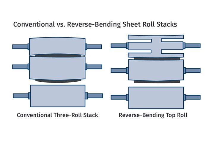
Reverse-bending top roll is center supported rather than end supported. It can bend to match the deflection of the center roll—opposite to the usual direction of top-roll deflection—thus maintaining uniform sheet gauge. Deflection is exaggerated here for visual clarity. (Image: J. Frankland)
Also, it has become common for sheet-line manufacturers to use a smaller-diameter top roll to facilitate ease of “string up” and provide additional safety to the operating people, because they do not have to reach through the nip. This further increases the deflection of the top roll. However with the top roll bending in the same direction as the middle roll, a much smaller top roll is easily available with no sacrifice in sheet gauge.
The drawing shows roll deflections exaggerated for clarity. In most cases, the roll deflection of both the conventional top and middle roll is each less than 0.002 in., but added together is 0.004 in., which is unacceptable for many high-tolerance sheet products. It is helpful to know the inner and outer shell thicknesses of the middle roll to match the reverse-bending roll as closely as possible; but this is not absolutely necessary, since as it can be closely approximated from the resulting sheet-gauge variation with an existing middle roll.
ABOUT THE AUTHOR: Jim Frankland is a mechanical engineer who has been involved in all types of extrusion processing for more than 40 years. He is now president of Frankland Plastics Consulting, LLC. Contact jim.frankland@comcast.net or (724)651-9196.
Related Content

How Much L/D Do You Really Need?
Just like selecting the extruder size and drive combination, the L/D should be carefully evaluated.
Read More
How to Get Rid of Bubbles in Injection Molding
First find out if they are the result of trapped gas or a vacuum void. Then follow these steps to get rid of them.
Read More
Tunnel Gates for Mold Designers, Part 1
Of all the gate types, tunnel gates are the most misunderstood. Here’s what you need to know to choose the best design for your application.
Read More
Understanding Strain-Rate Sensitivity In Polymers
Material behavior is fundamentally determined by the equivalence of time and temperature. But that principle tends to be lost on processors and designers. Here’s some guidance.
Read MoreRead Next

People 4.0 – How to Get Buy-In from Your Staff for Industry 4.0 Systems
Implementing a production monitoring system as the foundation of a ‘smart factory’ is about integrating people with new technology as much as it is about integrating machines and computers. Here are tips from a company that has gone through the process.
Read More
How Polymer Melts in Single-Screw Extruders
Understanding how polymer melts in a single-screw extruder could help you optimize your screw design to eliminate defect-causing solid polymer fragments.
Read More